Module 4. Alternators
Lesson 14
CONSTRUCTION AND TYPES OF ALTERNATORS
14.1 Introduction
Electrical machines (generators and motors) operated by alternating current are known as synchronous machines. An alternator is an electromechanical device that converts mechanical energy to electrical energy in the form of alternating current. A.C. generators are also called as alternators. A.C. generators are used in to generate electricity in hydroelectric (Fig. 14.1) and thermal plants. Alternators are also used in automobiles to generate electricity (Fig. 14.2).
|
|
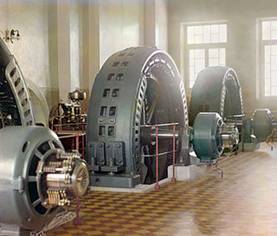
Fig. 14.1 Alternator/A.C. generator in a hydroelectric station
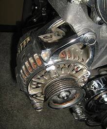
Fig. 14.2 Alternator mounted on an automobile engine
14.2 Construction
A.C. generator has mainly two parts
a. Stator
b. Rotor
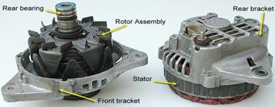
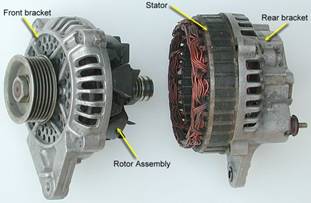
Fig. 14.3 Parts of an alternator
14.2.1 Stator
The Stationary part of the alternator is known as stator. It provides housing and support for the rotor. Slots are provided in the inner side of the stator to fix poles or windings (Fig. 14.4).
Fig. 14.4 Slots in stator
14.2.2 Rotor
It is the rotating part of an alternator.
14.3 Terms used in Alternator
1. Armature− The part of the alternator where emf is induced.
2. Winding- Insulated copper wires are wound over steel structure to induce magnetic field when current is supplied.
3. Slip rings- Two rings are provided to supply current to the rotor winding.
4. Brushes-The brushes rest on the slip ring to provide contact for supplying current.
5. Pole-Made of cast iron or steel of good magnetic quality. Act as north or South Pole alternately.
6. Prime mover- The mechanical system to provide rotation to the alternator is known as prime mover
14.4 Arrangement of Synchronous Generator
Two possible arrangement of armature in an alternator are:
1. Stationary armature winding and rotating poles.
2. Stationary poles and rotating armature winding.
14.4.1 Stationary armature winding and rotating poles
The stator is provided with slots where the armature winding along with the insulation is placed. The rotor has magnetic poles arranged alternately as North (N) and South (S). The numbers of poles vary according to the speed of the prime mover.
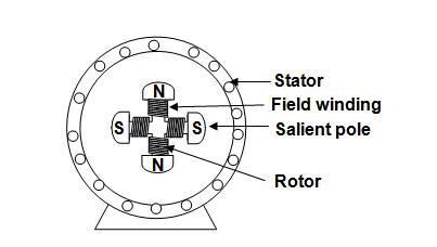
Fig. 14.5 Salient pole type alternator
14.4.2 Stationary poles and rotating armature winding
In this type of arrangement the poles are fixed in the stator and the armature winding is provided on the rotor.
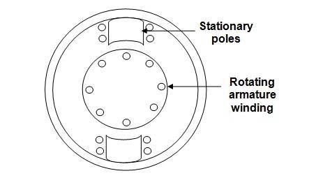
Fig. 14.6 Stationary poles and rotating armature winding
First type of arrangement i.e. stationary armature winding and rotating poles are preferred over the second arrangement (stationary poles and rotating armature winding) because of the following reasons:
1. More space is available for armature windings, therefore more coils and insulator can be provided. This allows achieving voltages as high as 33kV.
2. Less number of slip rings is required.
3. Simple in design and construction.
4. Less rotor weight and reduced mechanical power required to move rotor.
5. Reduced chances of burning of windings.
When an alternator is operated heat is generated in the windings. Slots and fan are provided for air circulation. This helps in ventilation and removal of heat from the windings and thus protects the armature winding.
14.5 Rotor Construction
Rotors are of two types:
1. Salient (or projected) pole type.
2. Smooth cylindrical or non-salient type.
14.5.1 Salient (or projected) pole type.
As the name suggests, the poles are made with projections. This type of rotor is used for low to medium speed/rpm alternators, were more number of poles are required may be 20 or 30 poles. Such alternator can be identified by large diameter and short length. The pole is made of steel or cast iron and the pole winding is excited by a D.C. generator driven by the shaft of alternator.
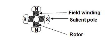
Fig. 14.7 Salient pole type rotor
14.5.2 Smooth cylindrical or non-salient type rotor
Such rotors are used for high speed alternators. The rotor is made of steel cylinder with number of slots cut on the periphery of the cylinder. The field windings are placed in the slots. The chart area acts as the pole. These axial alternators have more length and smaller diameter.
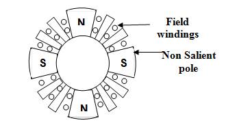
Fig. 14.8 Smooth cylindrical or non salient type rotor
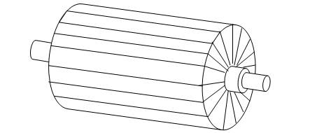
Fig. 14.9 3D view of smooth cylindrical or non-salient type rotor