Module 4. Alternators
Lesson 15
PRINCIPLES OF ALTERNATORS
15.1 Principle of Operation
In alternators, a rotating magnet, called the rotor turns within a stationary set of conductors wound in coils on an iron core, called the stator. The field cuts across the conductors, generating an induced EMF (electromotive force), as the mechanical input causes the rotor to turn.
The rotating magnetic field induces an A.C. voltage in the stator windings. Often there are three sets of stator windings, physically offset so that the rotating magnetic field produces a three phase current, displaced by one-third of a period with respect to each other.
The rotor's magnetic field may be produced by induction (as in a "brushless" alternator), by permanent magnets (as in very small machines), or by a rotor winding energized with direct current through slip rings and brushes. The rotor's magnetic field may even be provided by stationary field winding, with moving poles in the rotor. Permanent magnet machines avoid the loss due to magnetizing current in the rotor, but are restricted in size, due to the cost of the magnet material. Since the permanent magnet field is constant, the terminal voltage varies directly with the speed of the generator.
An automatic voltage control device controls the field current to keep output voltage constant. If the output voltage from the stationary armature coils drops due to an increase in demand, more current is fed into the rotating field coils through the voltage regulator (VR). This increases the magnetic field around the field coils which induces a greater voltage in the armature coils. Thus, the output voltage is brought back up to its original value.
According to Faraday’s laws of electromagnetic, induced emf is generated when a coil is rotated in any magnetic field. The magnitude of the induced emf in the coil rotating in a magnetic field in given as:
emf (e) = B l v N sin θ
Where,
e = induced emf in volt.
B = Magnetic field flux density, Wb/m2
l = length of the wire in the coil.
v = Velocity of rotation
N = Number of turns in the coils.
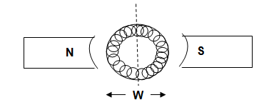
Fig. 15.1 Two sides of coil in an alternator
Since the coil has two sides (Fig. 15.1):
Total emf generated e = 2 B l v N sin θ
Since the angular velocity of the spinning coil is ω = v/r and in this case r = W/2, then v = ωW/2 . ω is in radians/sec, so if θ = 0 at t = 0, then θ = ωt , and our expression for e becomes,
e = 2BLv sin θ
= 2BL(ωW/2) sin ωt
= (LW)Bω sin ωt
Where,
W = width of the coil
L = length of the coil
N = Number of turns or loops
For a coil of N loops and identifying A = LW (valid for any planar shape),
e = NABω sin ωt
= eo sin ωt
Where,
eo = maximum emf = NABω
An A.C. generator converts mechanical energy into electrical energy. The mechanical system to provide rotation to the alternator is known as the prime mover (Fig. 15.2). Thus an alternator can be operated using a steam turbine, hydraulic turbine or a diesel/kerosene engine.
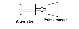
Fig. 15.2 Prime mover for an alternator
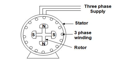
Fig. 15.3 3∅ alternator
Fig 15.3 shows a 3∅ alternator. When the rotor rotates, the stator winding are cut by the magnetic flux of the poles. Since the poles are arranged alternately North (N) and South (S) on the rotor the emf induced is of alternating type.
15.2 Relationship between Speed, Frequency and Number of Poles.
Following equation gives the relation between speed, frequency and
number of poles
![]()
Where
P = no. of poles
N = r.p.m.
The output frequency of an alternator depends on the number of poles and the rotational speed. The speed corresponding to a particular frequency is called the synchronous speed for that frequency (Table 15.1).
Table 15.1 Rotational speed and poles required for producing A.C. at different frequencies
|
Poles |
r.p.m for 50 Hz |
r.p.m for 60 Hz |
r.p.m for 400 Hz |
|
2 |
3,000 |
3,600 |
24,000 |
|
4 |
1,500 |
1,800 |
12,000 |
|
6 |
1,000 |
1,200 |
8,000 |
|
8 |
750 |
900 |
6000 |
|
10 |
600 |
720 |
4800 |
|
12 |
500 |
600 |
4000 |
|
14 |
429 |
515 |
3429 |
|
16 |
375 |
450 |
3000 |
|
18 |
333 |
400 |
2667 |
|
20 |
300 |
360 |
2400 |
|
40 |
150 |
180 |
1200 |
In India the frequency of alternating current is 50 Hz. This value is the standard frequency for generation and distribution of electricity. Electrical appliances are designed accordingly to work at 50 Hz.
Suppose a steam turbine rotates at 1000 rpm. Number of poles required in an alternator to generate 50 Hz alternator current is:
![]()
![]()
![]()
Similarly table 15.2 denotes the rotational speed required for alternator with different number of poles for producing a.c. at 50 Hz:
Table 15.2 Rotational speed and poles required for producing a.c. at 50 Hz frequency
|
No. of poles in alternator |
2 |
4 |
6 |
8 |
10 |
12 |
16 |
20 |
|
Speed (rpm) |
3000 |
1500 |
1000 |
750 |
600 |
500 |
375 |
300 |
Numericals
1. Calculate the frequency of the alternating current if speed = 300 rpm and numer of poles = 8.
![]()
Where
P = no. of poles
N = r.p.m.
![]()
2. A generator with a circular coil of 75 turns of area 3.0 x 10⁻² m2 is placed in a 0.20 T magnetic field and rotated with a frequency of 60 Hz. Find the maximum emf which is produced during a cycle.
Solution:
N = 75, A = 3.0 x 10⁻² m2, B = 0.20 T and f = 60 Hz .
Since ω = 2πf = 2π(60) = 377 radians/s
eo = (75)(3.0
x 10-2)(0.20)(377) = 170 V