Module 5. Induction motors
Lesson 20
PERFORMANCE CHARACTERISTICS OF INDUCTION MOTORS
20.1 Important Terms and Definitions
20.1.1 Torque
Torque is the turning force through a radius and the units is in Nm.
20.1.2 Slip
The difference between synchronous speed and rotor speed is called slip speed or simply slip:
Slip speed (S) = Ns−N
And T ∝ S
From above equation greater the slip greater will be the induced e.m.f. and thus motor will develop higher torque.
20.2 Expression for Torque
Torque developed by an induction motor is given by the following equation:
![]()
Where,
m = number of phases
S = Slip
E2s = Induced emf in rotor when rotor is stationary
R2
= Resistance of rotor
![]()
X2s = Leakage reactance of rotor when rotor is stationary
20.3 Condition for Maximum Torque
Condition for maximum torque is given by,
R2 = S X2s ......... (Eq. 1)
Where,
R2 = Resistance of rotor
S = Slip
X2s = Leakage reactance of rotor when rotor is stationary
Or, Slip S = R2/X2s ......... (Eq. 2)
Substituting value of equ. 2 into expression for torque in section 20.2,
![]()
From the above equation it is evident that to achieve higher torque, the value of leakage reactance of the rotor should be minimum. Therefore rotor conductors are placed close to the outer periphery of the rotor and the air gap between rotor and stator is kept as small as possible.
20.4 Starting Torque
At start of motor rotor is stationary and the value of slip (Ns−N) is one i.e. S=1. Thus,
![]()
Where,
m = number of phases
E2s = Induced emf in rotor when rotor is stationary
R2
= Resistance of rotor
![]()
X2s = Leakage reactance of rotor when rotor is stationary
We know Condition of maximum torque, R2 = S X2s and for heavy loaded induction motors, sometimes maximum torque is required at start. For maximum torque during starting placing S= 1
R2 = X2s
To obtain maximum torque at start, the value of rotor resistance must be equal to rotor leakage reactance at standstill. External resistance is added in the rotor circuit at the start of motor to get higher torque. Addition of variable resistance is only possible in case of slip ring induction motors. Therefore slip ring induction motors used for heavy loads applications like in cranes, conveyors, mechanical jacks, elevators etc.
20.5 Torque-Slip Characteristics
Torque-slip curve can be plotted (fig. 20.1) by considering different cases for the following torque expression discussed in section 20.2:
![]()
Case 1: When rotor speed N = Synchronous speed Ns
Slip S = 0 and Torque T = 0
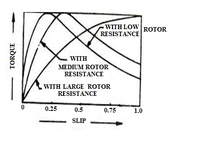
Fig. 20.1 Torque slip characteristics
Case 2: When rotor speed N close to Synchronous speed Ns i.e. very low slip
When S is very small SX2s << R2 then SX2s can be neglected.
From torque equation:
![]()
![]()
![]()
![]()
Where
K = constant
![]()
Or, ![]() S
S
Thus at very small value of slip S, torque (T) is directly proportional to S and straight line can be observed.
Case 3: Maximum value of torque
When Slip S = R2/X2s
Case 4: At high slip
When value of slip increases further
beyond the maximum torque value of slip, ![]()
Or, ![]()
![]()
![]()
![]()
At higher value of slip, torque is inversely proportional to slip.
20.6 Torque Speed Characteristics
It's important to understand some details of motor performance as shown by a typical Torque-Speed curve in the Figure 20.2. The plot shows what happens in terms of output torque and motor speed when a motor is started with full voltage applied. The motor is initially at zero speed and develops locked-rotor torque (Point A). As the motor accelerates, some motor designs produce a slight dip in torque. If they do, the lowest point on this curve is called the pull-in or pull-up torque (Point B). As the speed increases further, the torque generally increases to the highest point on the curve (Point C), which is called the pullout or breakdown torque. Finally, when the motor is loaded to its full-load torque, the motor speed stabilizes (Point D). If the motor isn't driving anything, its speed goes up to its no-load speed or synchronous speed (Point E). For example, on a four-pole motor operating at 60 Hz, the no-load speed might be 1,799 RPM and synchronous speed would be 1,800 RPM. Each of these points (A, B, C, and D) has absolute values (usually expressed in pound-feet). However, they're frequently given in terms of a percentage of the full-load torque. Torque speed curve varies when external resistance is added to the rotor winding (Fig. 20.3).

Fig. 20.2 Torque speed curve for induction motor
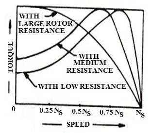
Fig.20.3 Torque speed curve for induction motor
20.7 Losses in an Induction motor
The major losses in an induction motor can be classified as stator and rotor losses (Fig. 20.4 and Table 20.1):
20.7.1 Stator losses
Losses occurring in the stator of an induction motor are called stator losses.
i. Stator copper losses – I21 R1 per phase
ii. Stator iron losses – Hysteresis and eddy current losses.
20.7.2 Rotor losses
Losses occurring in the rotor of an induction motor are called rotor losses.
i. Rotor copper losses – I22 R2 per phase
ii. Rotor iron losses –These losses small and can be neglected.
20.7.3 Mechanical losses
The sums of winding and friction losses are called mechanical losses.

Fig. 20.4 Losses in an Induction motor
Table 20.1 Percentage of losses in an induction motor
|
Name |
Percent of total loss Losses |
Description |
Fixed or Variable |
How to reduce |
|
Core Losses |
15-15% |
Energy required to magnetize core. |
Fixed |
Improved permeability steel, lengthening core, using thinner laminations in the core. |
|
Windage and Friction |
5-15% |
Losses due to bearing friction and air resistance, which is primarily caused by the cooling fan. |
Fixed |
Lower friction bearings, improve fan design and air flow. |
|
Stator Losses |
25-40% |
Heating due to current flow through the resistance of the stator winding. |
Variable |
Increasing the volume of copper wire in the stator, through improved stator slot designs, and by using thinner insulation. |
|
Rotor Losses |
15-25% |
Heating due to I2R losses in the rotor conductive bars. |
Variable |
Increasing the size of rotor conductive bars and end rings to reduce resistance. |
|
Additional Load Losses |
10-20% |
Leakage fluxes induced by load currents and various other minor losses. |
Variable |
Various design and manufacturing details. |