Module 5. Induction motors
Lesson 21
STARTING AND SPEED CONTROL OF INDUCTION MOTOR
21.1 Need of a Starter
The main problem in starting induction motors having large or medium size lies mainly in the requirement of high starting current when directly started from the main supply. As a consequence there will be a large voltage drop in the distribution line and will affect operation of other electrical machines, which is undesirable. Purpose of the starter is to limit the initial peak current drawn by the induction motor.
21.2 Starters for Squirrel Cage Induction Motors
Starters for squirrel cage induction motors can be classified as follows:
1. Direct On Line (D.O.L) Starter;
2. Star/Delta Starter;
3. Auto-transformer Starter.
21.2.1 Direct on line (D.O.L) starter
In this method stator is directly connected to the main power supply. The current drawn by motor, depending on its design class, will be from 5 to 7 times the nominal current rating. Since this amount of current flows only for a short period of time, it would not damage the squirrel cage motor, but it may cause undesirable drop in supply voltage, power factor and subsequently affects the performance of other equipment connected to the same supply. For this reason, the supply authorities limit the size of motor upto 5 H.P. which can be started by this starter.
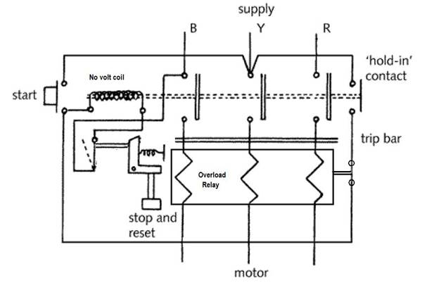
Fig. 21.1 Direct online starter
A direct on line Starter essentially consists of a contactor having four normally open (N.O.) contacts and a energizing coil also known as no-volt coil. The function of this coil is to keep together the N.O. contacts when starter is switched on. In case power supply fails, no-volt coil de-energizes and the circuit is open. The motor will not start automatically if the power supply is resumed and starter has to be switched ON once gain. Two push buttons ON and OFF are provided on the starter to start and stop the motor. To protect motor against overload, thermal or magnetic over-load coils are connected in each phase.
21.2.1.1 Start condition
ON button of starter completes the circuit of the no volt coil and it is energized. The four N.O. contacts are brought together by the bar connected to no volt coil and the motor starts.
21.2.1.2 Stop condition
To stop the motor, OFF push button is pressed which de-energies the no volt coil opening the main contacts.
21.2.2 Star-delta starter
This
method is used for motors that are designed to operate with Δ (delta)
connection. The components normally consist of three contactors, an overload
relay and a timer for setting the time in the star-position at starting
position (Fig. 21.2). The phases of stator are initially (star) connected using
a relay switch (K3). Once up to a particular running speed a double throw
switch (K2) changes the winding arrangements from Y to Δ whereupon full
running torque is achieved (Fig. 21.3). In this method the starting voltage
across each phase is VL/![]() and
thus the starting current is lower which leads to a smaller starting torque.
Such an arrangement means that the ends of all stator windings must be brought
to terminations outside the casing of the motor. The starter is provided with
overload and under voltage protection devices.
and
thus the starting current is lower which leads to a smaller starting torque.
Such an arrangement means that the ends of all stator windings must be brought
to terminations outside the casing of the motor. The starter is provided with
overload and under voltage protection devices.
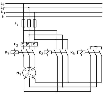
Fig. 21.2 Star-delta starter
L: Line conductor
N: Neutral conductor
F1: Fuses
F2: Thermal overload cut-out
K1: Main contactor
K2: Delta contactor
K3: Star contactor
M1: Three-phase motor
Fig. 21.3 Start and running configuration of rotor winding
The received starting current is about 30 % of the starting current during direct on line start and the starting torque is reduced to about 25 % of the torque available at a D.O.L start. This starting method only works when the application is light loaded during the start. If the motor is too heavily loaded, there will not be enough torque to accelerate the motor up to speed before switching over to the delta position. When starting up, the load torque is low at the beginning of the start and increases with the square of the speed. When reaching approximately 80-85% of the motor rated speed the load torque is equal to the motor torque and the acceleration ceases. To reach the rated speed, a switch over to delta position is necessary, and this will very often result in high transmission and current peaks. In some cases the current peak can reach a value that is even bigger than for a D.O.L start. Applications with a load torque higher than 50% of the motor rated torque will not be able to start using the star-delta starter.
21.3.3 Auto transformer starter
This is another starting method that reduces the starting current and starting torque but contrary to Star-Delta starting where this starting method needs three wires and three terminals on the motor. Autotransformers are generally equipped with taps at each phase in order to adapt the starting parameters to the application starting requirement. During starting, the motor is connected to the autotransformer taps. With the star and autotransformer contactors closed, the motor is under reduced voltage. Consequently the torque is reduced as the square of the applied voltage. When the motor reaches the 80 to 95% of the nominal speed, the star contactor opens. Then the line contactor closes and the autotransformer contactor opens. The motor is never disconnected from the power supply during starting (closed transition) and reduces transient phenomena. Taps on the autotransformer allow for selection of the motor with 50%, 65%, or 80% of the current inrush seen during a full voltage start. The resulting starting torque will be 25%, 42%, or 64% of full voltage values, as will be the current draw on the line. Thus, the autotransformer provides the maximum torque with minimum line current.
In this method, quite less current is drawn from supply as compared to previous method, but the extra equipment is still required. On the other hand, the starting torque is small as a result of low amount of voltage at starting instant, so this method is not useful for high inertia loads.

AT: Auto transformer 1, 2, 3: Switches
Fig. 21.4 Auto transformer starter
21.4 Starting Method of Slip Ring Induction Motor
If it is necessary to start a three phase induction motor on load then a wound rotor machine also known as slip ring motor will normally be selected. Such a machine allows an external resistance to be connected to the rotor of the machine through slip rings and brushes. A 3-phase rheostat is connected in series with the rotor circuit through brushes (Fig.21.5). At start-up the rotor resistance is set at maximum but is reduced as speed increases until eventually it is reduced to zero and the machine runs as if it is a cage rotor machine. By inserting external resistance in the rotor circuit, not only the starting current is reduced but at the same time starting torque is increased due to improvement of power factor.
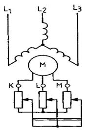
Fig. 21.5 Starting of slip ring induction motor using variable resistance
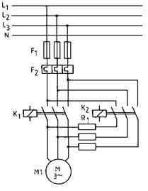
Fig. 21.6 Starting of slip ring induction motor using fixed starting resistance
L: Line conductor
N: Neutral conductor
F1: Fuses
F2: Thermal overload cut-out
K1: Main contactor
K2: Resistance circuit contactor
R1: Starting resistance
M1: Three-phase motor
21.5 Soft Starter
When starting, an AC Induction motor develops more torque than is required at full speed. This stress is transferred to the mechanical transmission system resulting in excessive wear and premature failure of chains, belts, gears, mechanical seals, etc. Additionally, rapid acceleration also has a massive impact on electricity supply charges with high inrush currents drawing +600% of the normal run current (Fig. 21.7). The use of Star Delta only provides a partial solution to the problem. If the motor slow down during the transition period, the high peaks are repeated and can even exceed direct on line current.
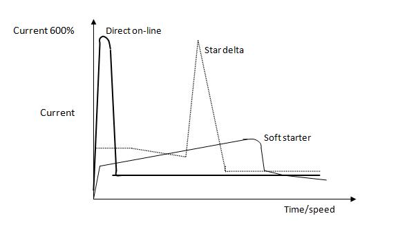
Fig. 21.7 Comparison of current drawn by DOL, Star delta and soft start methods
A soft starter shown in fig. 21.8 is a solid state motor starter that is used to start or stop a motor by notching the voltage waveform, thereby, reducing the voltage to each phase of a motor and gradually increasing the voltage until the motor gets up to full voltage/speed all at a fixed frequency. The profile of the increase of voltage depends on the application. The voltage is reduced and controlled by 3 pairs of back-to-back silicon-controlled rectifiers (SCRs), which are a type of high speed thyristor. A soft starter takes the place of a contactor and can also take the place of an overload relay in a standard motor starting application.
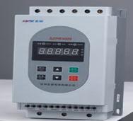
Fig. 21.8 Soft starter
In general, there are two reasons to use a soft starter: the power distribution network may not be able to handle the inrush current of the motor and/or the load cannot handle the high starting torque. As a rule of thumb, a motor utilizes around 600-800% of its full load current (FLA) to start. This current is referred to as inrush current or locked-rotor current. If a large motor is on a smaller power distribution network or on a generator system, this inrush current can cause the system voltage to dip, or to “brown out”. Brown outs can cause problems with whatever else is connected to the system, such as computers, lights, motors, and other loads. Another problem is that the system may not even be able to start the motor because it cannot source or supply enough current. Most industrial businesses run during the day can be fined or charged extra (Maximum Demand Charges) during this peak usage time for large transients caused by large horsepower (hp)/Kilowatt (kW) motor start ups. These Maximum Demand Charges can add up very quickly, especially if the motor needs to be started multiple times during any given day. The inrush current can be controlled one of two ways with a soft starter: either with a current limit (discussed later) or reduced linearly with the reduced voltage
21.6 Comparison of Different Starting Methods
21.6.1 Direct on-line starting
· Three-phase motor with low to medium power rating
· 3 conductors to the motor
· High starting torque
· High current peak
· Voltage dip
· One simple switching device
21.6.2 Star-delta start-up
· Three-phase motor with low to high power rating
· Six conductors to the motor
· Reduced starting torque, 1/3 of the nominal torque
· High mains load due to current peak during switchover from Y to Δ
· High mechanical stress due to torque surge during switchover from Y to Δ
· Two or three switching devices, more maintenance
21.6.3 Autotransformer starter
· lower relative cost (costs about 66% of a similar sized solid-state starter)
· Includes solid-state motor protection relays and vacuum contactors.
· Disadvantages include its non-continuous acceleration and inflexibility
21.6.4 Starting method using external resistance (Slip ring induction motor)
· Additional resistance is used only for starting,
· Resistance is rated for intermittent duty,
· Resistance is to be decreased in steps, as the motor speed increases.
· Finally, the external resistance is to be completely cut out.
· Additional cost of the external resistance is to be incurred,
· Decrease of starting current, along with increase of starting torque both being advantageous
· Only used in case higher starting torque is needed to start induction motor with high load torque.
21.6.5 Soft start-up
· Three-phase motor with low to high power rating
· 3 conductors to the motor
· Variable starting torque
· No current peak
· No torque peaks
· Negligible voltage dip
· One simple switching device
· Optional: Guided soft stop, protective functions, etc.
·
Zero
maintenance