Module 6. D.C. machines
Lesson 24
TYPES AND CHARACTERISTICS OF D.C. MOTORS-I
24.1 Introduction
D.C. motor is used to convert electrical energy into mechanical energy. The shaft of the motor rotates when current is supplied to the motor. Motor are used to operate pumps, lifts, cranes etc. The construction of D.C. motor is similar to a D.C. generator. When the armature and field winding of a D.C. generator is connected to a D.C. Source (e.g. battery) it will work like a motor. The advantages of a D.C. motor includes low initial cost, ease in speed control, high initial torque. D. C. motors require more maintenance and have less useful life.
24.2 Types of D.C. MOTOR
D.C. motors can be classified into three types according to the connection of field windings to the armature windings:
1. Shunt wound motor
2. Series wound motor
3. Compound wound motor
24.2.1 Shunt wound motor
Here the field windings are connected in parallel with the armature.
· For constant applied voltage, the field current is constant.
· The speed of the shunt wound makes it almost constant as the flux and back emf are constant. Therefore it is also considered constant speed machine.
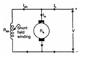
Fig. 24.1 Shunt wound motor
24.2.2 Series wound motor
Since the field winding and armature are connected in series.
![]()
One of the characteristic and advantage of D.C. motor is that as the motor is loaded heavily, the speed of the motor automatically gets reduced.
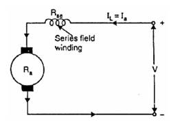
Fig. 24.2 Series wound motor
24.2.3 Compound motor
In compound wound motor the field (pole) winding comprise of two windings:
a. Shunt field winding
b. Series field windings
The
field windings connected in series and shunt this produce the resultant flux to
drive the motor. D.C. compound motor is a combination of the series and the
shunt motor. The series field winding is connected in series with the armature
and a shunt field is in parallel with the armature. The combination of series
and shunt winding allow the motor to have the torque characteristics of the
series motor and the regulated speed characteristics of the shunt motor.
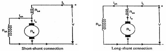
Fig. 24.3 Compound motor
24.3 Back E.M.F in D.C. Motors
When the motor is operated magnetic flux is produced by the field winding and armature winding. The flux produced at the field winding is also known as main flux. As the armature rotates the windings of the armature (also known as conductor) cuts the flux. Thus an e.m.f is induced in the armature winding whose direction is opposite to the applied voltage. The induce e.m.f is opposite in direction and opposes the applied voltage, it is also known as back e.m.f.
Thus relation between applied voltage and back e.m.f is given as follows:
![]()
Where,
V = applied voltage
Eb = back e.m.f
Ia = armature current
Ra = armature resistance
24.4 Motor Torque
24.4.1 Torque
It is also known as moment of force. Torque is the tendency of a force to rotate an object about an axis or pivot. Force is defined as push or pull; similarly a torque can be thought of as a twist.

Fig. 24.4 Shaft of radius r
Consider a shaft of radius r which is rotated by its axis by force F acting on the circumference of the shaft (Fig. 24.4).
![]()
Where
T = Torque
r = radius of shaft
(Or the distance from the axis to the application of force)
F = applied force
24.4.2 Machine torque
One of the basic specifications of an engine is Torque. The power output of an engine can be given as:
Power developed P = Torque × rotational speed
![]()
![]() ………
(1)
………
(1)
Where
P = Power developed
T = Torque
ω = angular velocity in radian/second.
N = rpm (rotation per minute)
24.4.3 Torque in a motor
From equation 1, power developed is given as:
![]() ……… (2)
……… (2)
Where,
Ta = Torque developed by the armature
Electrical equivalent of mechanical power developed by the armature is given by
![]() ………
(3)
………
(3)
Where,
Eb = back e.m.f
Ia= armature current
Equating equation (2) and (3)
![]() ……… (4)
……… (4)
![]() ………
(5)
………
(5)
Where,
∅ = flux/pole in Weber’s
Z = total number of armature
conductors
= number of slots × conductors/ slot
N = armature rotation r.p.m
P = number of poles
a = number of parallel paths in armature
Placing value of equation (5) into equation (4)
![]()
Arranging,
![]()
Since Z, p and a are constant for any motor
![]()
Case 1: For shunt motors
∅ i.e. flux per pole is changing,
![]() ………
(6)
………
(6)
Since Z, p and a are constant for any motor.
![]()
Case 2: For series motors
Since field windings carry full armature current, ∅ is directly proportional to Ia before saturation.
![]()
24.4.4 Shaft torque (Tsh)
The armature torque developed in the motor is not fully available to the shaft due to iron and friction losses. The torque available at the shaft will be always lower than the armature torque.
![]()
![]()
The horse power at the shaft is known as brake horse power (B.H.P). B.H.P is calculated using shaft torque.
![]()
![]()
Note1: The Brake Power mentioned here is metric brake horse power.
1 B. H. P (metric) = 735.5 watt
Do not confuse with Electrical horse power which is equivalent to 746 watt.
Note 2: The
difference Tarmature – Tshaft is known as lost Torque.