Module 3. Pressure measuring devices
Lesson 5
SIMPLE MANOMETER, PIEZOMETER, U-TUBE MANOMETER
5.1 Introduction
There are many techniques for the measurement of pressure and vacuum. Instruments used to measure pressure are called pressure gauges. Manometers are used for the measurement of very low pressures as well as vacuum especially in hydraulic laboratories.
5.2 Manometers
Manometers are used for measuring pressures by balancing the fluid column of fluid against another column of fluid of known specific gravity. Manometers can be classified as:
1. Simple manometers
a. Piezometer
b. U-tube manometer
2. Micro manometers (or single column manometers)
a. Vertical column micro manometer
b. Inclined column micro manometer
3. Differential manometers
a. Upright U-tube differential manometer
b. Inverted U-tube differential manometer
1. Simple manometers
It consists of a glass tube with one end open to the atmosphere and other end connected to a point at which pressure is to be measured.
a. Piezometer
It consists of glass tube connected to a vessel or pipe at which static pressure is to be measured. It is the simplest of all the manometers (Fig. 5.1). It is used to measure very low pressures.
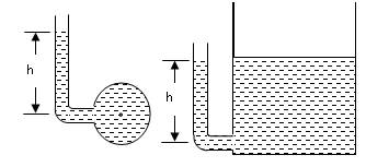
Fig. 5.1 Piezometer
The pressure in piezometer is given by the following equation.
![]()
Where,
![]() = density of liquid
= density of liquid
h = height of liquid in the piezometer from the centre of the pipe.
g = acceleration due to gravity.
b. U-tube manometer
The manometer is named so because it consists of a glass tube having the shape of alphabet 'U’. One end is open to the atmosphere and other end connected to a point at which pressure is to be measured.
Let ρ1 = density of liquid for which pressure has to be determined
ρ2 = density of manometer liquid (assume mercury)
ω1 = weight density of liquid for which pressure has to be determined
ω2 = weight density of manometer liquid
S1 = Specific gravity of liquid for which pressure has to be determined
S2 = Specific gravity of manometer liquid
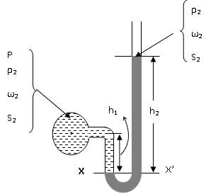
Fig. 5.2 U-tube manometer
Let ‘h’ be the pressure in terms of height of fluid in the pipe.
‘h1’ is the distance from the datum line XX’ to the centre of pipe
‘h2’ is the height of manometer liquid from the datum line XX’ in the right limb
Pressure in the left limb at XX’ = P + ρ1gh1 = P + ω1h1
Pressure in the right limb at XX’ = ρ2gh2 = ω2h2
According to Pascal’s law, at datum line pressure will be equal
P + ω1h1 = ω2h2
P = ω2h2 - ω1h1 ……… (i)
P = ρ2gh2 - ρ1gh1 ……… (ii)
On dividing equation (ii) by ρg where ρ is the density of the water:
![]() ………
(iii)
………
(iii)
Sp. Gravity (s) = ![]()
![]() ……… (iv)
……… (iv)
Since P = ρgh where ‘h’ is head of water
h = S2h2 – S1h1 ………
(v)
5.3 Rules for Writing Equations for Manometers
Step
1: Draw a neat diagram of a manometer
Step 2: Consider
a suitable datum line XX’. It should be in such a manner so that manometer
liquid touching the datum line in the two limbs is the same. At figure 5.3,
point A and B are on the datum line, liquids is same in both the columns i.e.
left and right limbs.
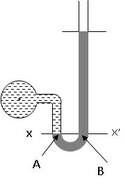
Fig. 5.3 Selection of datum line XX’
Step 3: Mark
the distances of centre of pipe and the liquid level in the vertical
column from the datum line X-X’
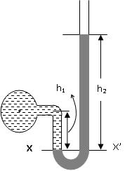
Fig. 5.4 Marking liquid levels
Step 4: Let
h in meters is the pressure head in the centre of pipe.
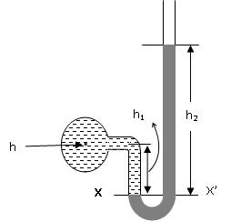
Fig. 5.5 Pressure
head h at the centre of pipe
Step 5: Write
the equation for pressure head in the left limb starting from center of pipe.
Pressure head in left limb
at X-X’ = h + h1S1
Where,
S1 =
Specific gravity of liquid for which pressure has to be determined
S2 =
Specific gravity of manometer liquid (assume mercury)
Let ‘h’ be the
pressure in terms of height of fluid in the pipe.
‘h1’
is the distance from the datum line XX’ to the centre of pipe
‘h2’
is the height of heavy liquid from the datum line XX’ in the right limb
Step 6: Write
the equation for pressure head in the right limb starting from center of pipe.
Pressure head in right limb
at X-X’ = h2S2
Step 7: Equate
the pressure heads in the two limbs (left and right) to get the value of h.
Equating
pressure head at X-X’ as the pressure at datum line would be equal.
h + h1S1 = h2S2
or,
h = h2S2
- h1S1
Note
1. Moving downward from a point in a manometer, all the
pressure heads will be added.
2. Moving upward from a point in a manometer, all the pressure
heads will be subtracted.