Module 5. Fluid flow
Lesson 13
BERNOULLI’S THEOREM
13.1 Introduction
Bernoulli’s Theorem is based on the conservation of energy in fluid flow. There are three types of energy namely potential energy, kinetic energy and pressure energy possessed by the liquid. The theorem explains how these energies change from one form to another form. Many instruments such as Pitot tube, Venturimeter etc. are working on the principle of Bernouilli’s theorem for the measurement of fluid flow.
13.2 Bernoulli’s Theorem
Bernoulli’s Theorem states that “in a steady ideal flow of in compressible fluid flow, the sum of pressure energy, kinetic energy and potential energy remains constant at every section provided no energy is added or taken out by an external source”
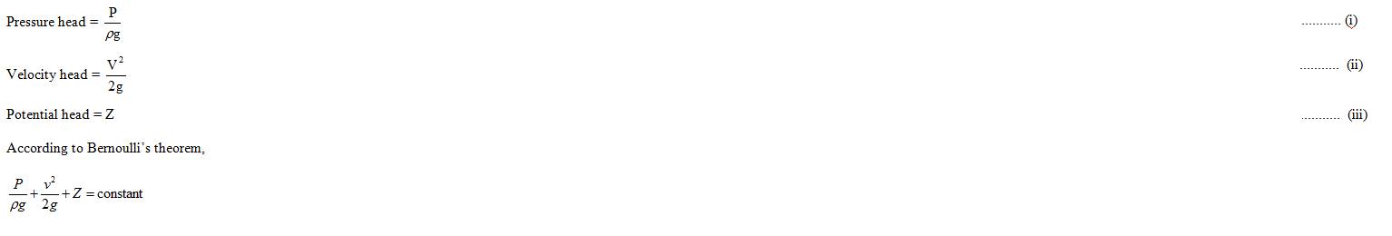
It is based on principle of conservation of energy and is expressed by the following relation:
Pressure energy + Kinetic energy + Potential energy = constant
Assumption for Bernoulli’s equation
Bernoulli’s theorem holds well under the following assumptions:
(1) The flow is along stream line.
(2) The flow is steady and continuous.
(3) The fluid is non-viscous (ideal fluid) and incompressible (ρ = constant).
(4)
Flow is irrotational.
Consider a pipe of varying diameter as shown in (Fig 13.1).
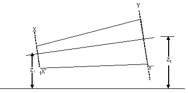
Fig. 13.1 Pipe of varying diameter
At section XX’
Cross sectional area of pipe = A1
Velocity of fluid = V1
Pressure of fluid = P1
At YY’
Cross sectional area of pipe = A2
Velocity of fluid = V2
Pressure of fluid = P2
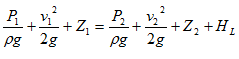
Applying Bernoulli’s theorem at section XX’ and YY’
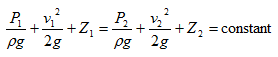
The
above equation holds true for an ideal fluid (i.e. when there is no loss of
head between two points). However, in practice some energy is lost due to
friction and it is denoted by HL then
13.3 Total Energy Line (TEL) and Hydraulic Grade Line (HGL)
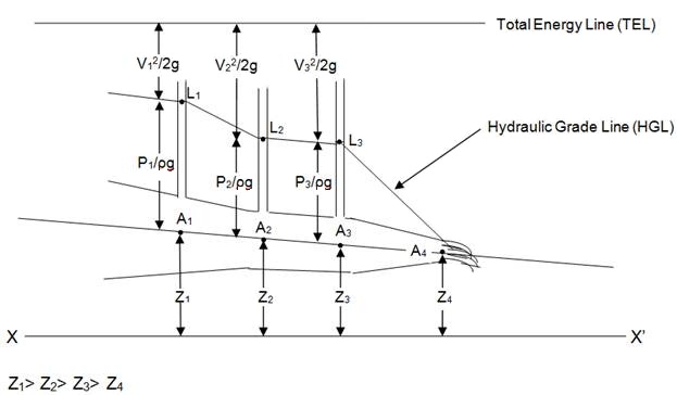
Fig. 13.2 Total Energy Line (TEL) and Hydraulic Grade Line (HGL)
(1) At points A1, A2 and A3, piezometer tube measures the pressure head (P/ρg) by rise of liquid in the peizometer tube h1, h2 and h3 respectively.
(2) Points A1, A2, A3 and A4 are located at a height of Z1, Z2, Z3 and Z4 above datum (reference line XX’). Z1, Z2, Z3 and Z4 are known as potential heads.
(3) Points L1, L2, and L3 represent the water level in the peizometer and are located at a height of (Z1+h1), (Z2+h2) and (Z3+h3).
(4) Point L4 is located at tip of nozzle is at height Z4 above datum line.
(5) The line joining points L1, L2, L3 and L4 is known as HGL and (P/ρg + Z) is known as hydraulic gradient.
(6) Total energy line is line joining points denoting total head is represented as

(7) At tip of nozzle (L4) the liquid is exposed to atmosphere as a result pressure head becomes zero.
(8) For flow in converging pipe there is a decrease in the pressure head (P/ρg) and consecutively there is a rise in velocity energy.
(9) At tip of nozzle pressure head and entire pressure energy gets converted into K.E. causing the flow velocity to increase.
13.4 Numericals
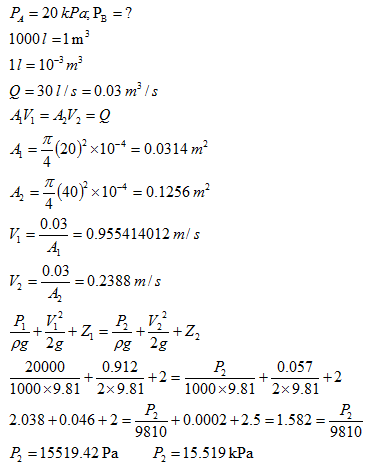
Q 1. Water is flowing through an inclined pipeline of diameter 20 cm & 40 cm at section A & B respectively. Section A & B are located at height of 2 m & 2.5 m respectively from ground level. The discharge through pipe is 30 l/s. If the pressure at A is 20 kPa, find the pressure at point B.
Solution:
1 Pa = 1 N/m2
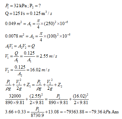
Q 2. A horizontal pipe of diameter 250 mm carries oil (sp. gravity = 0.89) at the rate of 125 l/s and a pressure of 32 kPa. The pipe converges to a 100 mm diameter at a section located in down stream. Determine the pressure at down stream.
Solution:
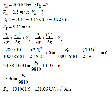
Q 3. The area of cross-section at point A in a converging pipe reduces from 0.45 m2 to 0.22 m2 at point B. The velocity & pressure at point A are 2.5 m/s and 200 kN/m2 respectively. Neglecting the frictional head loss in pipe, calculate the pressure at point B which is 6 m above the level of A.
Solution: