Module 5. Fluid flow
Lesson 14
APPLICATION OF BERNOULLI’S THEOREM
14.1 Introduction
Bernoulli’s theorem has number of applications. The working of many flow measuring devices are based on the principle of Bernoulli’s theorem. Some equations used in fluid mechanics are also derived using the concept of fluid mechanics. Some of the devices used for the measurement of fluid flow are as under.
1. Stagnation Tube
2. Stagnation Tube + piezometer
3. Pitot tube
4. Flow through nozzle from reservoir
14.2 Stagnation Tube
Stagnation tube is used to measure velocity in an open flow (Fig. 14.1).
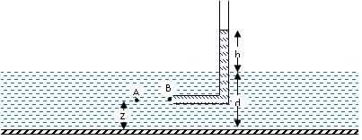
Fig. 14.1 Stagnation tube placed in an open channel flow
From Bernoulli’s theorem,
Applying Bernoulli’s theorem,
14.3 Combination of Stagnation Tube and Piezometer
As in the above case stagnation tube can be used along with a piezometer to measure velocity in closed pipe flow (Fig. 14.2).
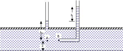
Fig. 14.2 Stagnation tube with a piezometer placed in a pipe (closed flow)
Note:
(1) The peizometer measures static pressure of fluid flowing in the pipe.
(2) The stagnation tube measures the stagnation pressure at any point in the fluid.
14.4 Pitot tube
Pitot tube is used for the measurement of fluid velocity. The construction of Pitot tube is shown in Fig. 14.3. Outer body of Pitot tube consists of ports at point A, for sensing the static pressure of fluid. At point B, fluid velocity becomes zero and inner tube is for sensing the stagnation pressure. The two ends of Pitot tube are connected to U-tube manometer for measuring the pressure difference between the points A and B.
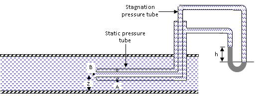
Fig. 14.3 Pitot tube
Note:
· Level of liquid in Pitot tube shows the position of total energy line (TEL). Pitot tube measures the total head and is therefore also known as total head tube.
· Level of liquid in piezometer represents the static pressure of the fluid and the position of hydraulic grade line (HGL).
· Pitot tube can be used to determine velocity distribution across the flow.
14.5 Flow Through Nozzle from Reservoir
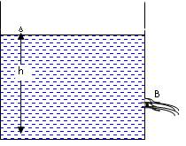
Fig. 14.4 Flow through nozzle from reservoir
Fig 14.4 shows a reservoir fitted with a nozzle on the side. Point A corresponds to free water surface and point B at the tip of nozzle of opening.
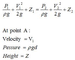
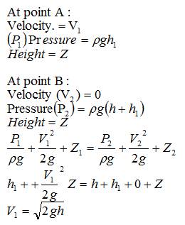
At point A
Velocity V1 = 0 (since the top water level is moving very slow compared to velocity of water at B.
Pressure (P1) = 0
Height of point A from datum line = h
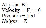
At point B
Velocity = V2
Pressure (P2) = 0
Height of point B from datum line = 0
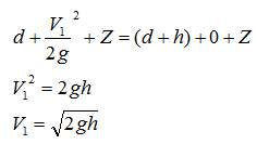
Apply Bernoulli’s Theorem:
![]()
V22 = 2gh
![]()