Module 10 . Pumps
Lesson 31
CENTRIFUGAL PUMP, PRESSURE VARIATION, WORK DONE, EFFICIENCY
31.1 Centrifugal Pump
Centrifugal pump uses a rotating impeller to increase the pressure of a fluid. Centrifugal pumps are very common in food and dairy processing industry. These pumps deliver large flow rate at low or medium head and are used for low viscous liquid like water, milk, juices, cream etc.
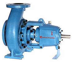
Fig. 31.1 Centrifugal pump
31.2 Construction of a Centrifugal Pump
Different parts of centrifugal pumps are as follows (Fig. 31.2):
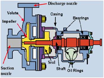
Fig. 31.2 Parts of a centrifugal pump
31.2.1 Rotating component
It consists of shaft and impeller. Shaft is coupled with a motor to give drive to the pump. An impeller is a rotating component of a centrifugal pump, usually made of iron, steel, bronze, brass or aluminium which transfers energy from the motor that drives the pump to the fluid being pumped by accelerating the fluid outwards from the center of rotation. Different types of impeller are:
Open type impeller: It consists of vane which accelerates the fluid. The number of vanes can vary from 2 to 8 or more.
Fig. 31.3 Open type impeller
Semi-closed impeller: It consists of vane attached to plate on one side. Industrial application of such types of impeller is for pumping liquids containing suspensions.

Fig. 31.4 Semi-closed impeller
Closed impeller: The vane is enclosed by two disc or plates. Shrouds or sidewall encloses the vanes. The liquid moves in between the cavity between the vanes and plates.
Fig. 31.5 Closed impeller
It can also be classified as based on major direction of flow in reference to the axis of rotation
1. Radial flow
2. Axial flow
3. Mixed flow
31.2.2 Casing
It is the cover housing the impeller. The rotating impeller increases the kinetic energy of the liquid. The casing helps to covert this kinetic energy into pressure energy. The main function of casing is to enclose the impeller at suction and delivery ends and thereby form a pressure vessel. The pressure at suction end may be as little as one-tenth of atmospheric pressure and at delivery end may be twenty times the atmospheric pressure in a single-stage pump.
The vanes of the rotating impeller impart a radial and rotary motion to the liquid, forcing it to the outer periphery of the pump casing where it is collected in the outer part of the pump casing called the volute. The volute is a region that expands in cross-sectional area as it wraps around the pump casing. Purpose of the volute is to collect the liquid discharged from the periphery of the impeller at high velocity and gradually cause a reduction in fluid velocity by increasing the flow area This converts the velocity head to static pressure. The fluid is then discharged from the centrifugal pump through the discharge connection.
32.2.2.1 Types of chamber/casing
Volute casing: This is named from the spiral shape of the casing which is so constructed to act as a collector for the liquid as it leaves the outer edge of the impeller vanes. In volute pumps area of flow gradually increases from throat towards the delivery pipe. The increase in area of flow decreases the exit velocity and hence pressure increases in the casing.

Fig. 31.6 Volute casing
Vortex: Vortex casing is a casing in which circular chamber is provided between the casing and the impeller. Vortex casing will increase pump efficiency by reducing eddies formation to a considerable extent.
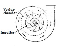
Fig. 31.7 Vortex
Diffuser: In diffuser casing, the fluid passes through a ring of fixed vanes or diffuser after the fluid has left the impeller, that diffuse the liquid, this provides a more controlled flow and a more efficient conversion of velocity head into pressure head. Providing fixed diffuser increases the efficiency of the pump up to 90 percent.
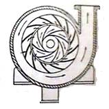
Fig. 31.8 Diffuser
31.2.3 Suction and delivery pipe
A pipe whose one end is connected to the inlet of the pump and other end dips into water in a pump is known as suction pipe. A foot value is a non- return value fitted at the lower end of the suction pipe which helps to fill water during priming. The suction pipe is connected to the opening (eye) of the impeller. Discharge pipe is provided on the pump casing to attach delivery side.
31.2.4 Bearing housing
The bearing housing encloses the bearings mounted on the shaft. The bearings keep the shaft or rotor in correct alignment with the stationary parts under the action of radial and transverse loads. The bearing house also includes an oil reservoir for lubrication, constant level of oil, jacket for cooling by circulating cooling water.
31.3 Working Principle of Centrifugal Pumps
The centrifugal pump operates by the transfer of energy (or angular momentum) from a rotating impeller to the fluid, which is normally inside a casing. The fluid enters at the axis or ‘eye’ of the impeller (which may be open or closed and usually contains radial curved vanes) and is discharged from the impeller periphery. On rotation of impeller, partial vacuum is created in the casing which causes the suction of liquid from the reservoir. The maximum possible suction lift is 10.3 m of water. The kinetic energy and momentum of the fluid are increased by the angular momentum imparted by the high-speed impeller. This kinetic energy is then converted to pressure energy (‘head’) in a diverging area (the ‘volute’) between the impeller discharge and the casing before the fluid exits the pump. The head that these pumps can develop depends upon the pump design and the size, shape, and speed of the impeller and the flow capacity is determined by the flow resistance of the system in which the pump is installed.
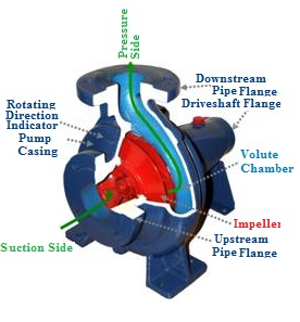
Fig 31.9 Cut view of centrifugal pump
Thus, these pumps operate at approximately constant head and variable flow rate within limits. Centrifugal pumps can be operated in a ‘closed off’ condition (i.e. closed discharge line), because the liquid can re-circulate within the pump without causing damage. However, such conditions should be avoided, because energy dissipation within the pump could result in excessive heating of the fluid and/or the pump or unstable operation, with adverse consequences. Centrifugal pumps are most appropriate for ‘ordinary’ (i.e. low to moderate viscosity) liquids under a wide variety of flow conditions and are thus the most common type of pump. The following discussion applies primarily to centrifugal pumps.
Priming of centrifugal pump
The operation in which the suction pipe, casing of pump and a portion of delivery pipe is filled by the outside source of liquid before starting the pump. Foot value is necessary at the end of suction pipe to fill water in the pipe for priming. This process removes air from impeller and casing necessary for pumping of liquid.
31.4 Few Important Terms
Capacity: It is the water handling capability of a pump commonly expressed as either cubic meter per minute (m3/min).
Cavitation: It is a phenomenon caused as a result of vapor bubbles imploding. This is the result of bubble formation at the suction point due to pressure difference.
Discharge Port: It is the point where the discharge hose or pipe is connected to the pump.
Datum: It is used as reference of the horizontal plane for which all the elevations and head are measured.
Dynamic Discharge Head: It is the static discharge head plus the friction in the discharge line also referred to as Total Discharge Head.
Dynamic Suction Head: It is the static suction lift plus the friction in the suction line also referred to as Total Suction Head.
Friction Head: It is the head required to overcome the resistance to flow in the pipe and fittings. It is dependent upon the size, condition and type of pipe, number and type of pipe fittings, flow rate, and nature of the liquid.
Friction Loss: It refers to the reductions in flow due to turbulence as water passes through hoses, pipes, fittings and elbows.
Priming: Most centrifugal pumps are not self-priming. In other words, the pump casing must be filled with liquid before the pump is started, otherwise the pump will not function. If the pump casing becomes filled with vapors or gases, the pump impeller becomes gas-bound and incapable of pumping. To ensure that a centrifugal pump remains primed and does not become gas-bound, it is necessary to attach a foot valve at the end of the suction pipeline.
31.5 Terminologies Associated to Pumping Systems
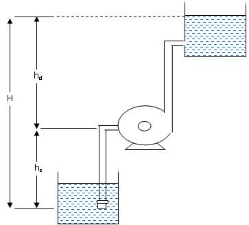
Fig. 31.10 Pressure variations in a pump
Static Suction Head (hs): It is the vertical distance between the centre of the impeller to the free surface of the water from where water is to be pumped. If the liquid level is above pump centerline, hs is positive. If the liquid level is below pump centerline, hs is negative. Negative hs condition is commonly denoted as a ‘suction lift’.
Static Discharge Head (hd): It is the vertical distance between the pump centerline and the point of free discharge or the surface of the liquid in the discharge tank.
Total Suction Head (hs): It is the suction reservoir pressure head (hps) plus the static suction head (hs) plus the velocity head at the pump suction flange (hvs) minus the friction head in the suction line (hfs).
HS = hps + hs + hvs + hfs
Total Discharge Head (hd): It is the sum total of discharge reservoir pressure head (hpd), static discharge head (hd), the velocity head at the pump discharge flange (hvd) and the total friction head in the discharge line (hfd).
hd = hpd + hd + hvd + hfd
Manometric head: It is defined as the head against which a centrifugal pump has to work.
![]()
Where,
hs = Suction head
hd = delivery head
hfs = Frictional head loss in suction pipe
hfd = Frictional head loss in delivery pipe
Vd = Velocity of pipe in delivery pipe
31.6 Pump Performance Curve
The main characteristic curves of a centrifugal pump consistes pf variation of head (hm), power (P) and discharge (Q) with respect to speed (Fig. 31.11) The operating characteristic curves is shown in fig. 31.12.
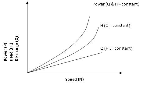
Fig. 31.11 Main characteristic curve
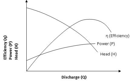
Fig. 31.12 Operating characteristic curves
31.7 Pump Efficiency
Pump efficiency, η (%) is a measure of the efficiency with which the pump uses the input power to convert the energy into useful output.
η = Pout/Pin
where
η = efficiency (%)
Pin = power input
Pout = power output
31.8 Water Horse Power (WHP) and Brake Horse Power (BHP)
The work performed by a pump is a function of the total head and the weight of the liquid pumped in a given time period. Pump input or brake horsepower (BHP) is the actual horsepower delivered to the pump shaft. Pump output or hydraulic or water horsepower (WHP) is the liquid horsepower delivered by the pump. These two terms are defined by the following formulas.
![]()
![]()
where:
BHP is the brake horse power required (W)
ρ is the fluid density (kg/m3)
g is the standard acceleration of gravity (9.81 m/s2)
H is the energy Head added to the flow (m)
Q is the flow rate (m3/s)
η is the efficiency of the pump (decimal)
![]()
The head added by the pump (H) is a sum of the static lift, the head loss due to friction and any losses due to valves or pipe bends all expressed in metres of fluid. Power is more commonly expressed as kilowatts (103 W) or horsepower (multiply kilowatts by 0.746). The value for the pump efficiency η may be stated for the pump itself or as a combined efficiency of the pump and motor system. The energy usage is determined by multiplying the power requirement by the length of time the pump is operating.
31.8 Pump selection criteria
Pump is selected on the basis of the following criteria:
a) Nature of liquid
· Type- Water, Beverage, Juice, milk, cream etc
· Density
· Viscosity
· Clear liquid/suspended
b) Capacity (m3/min or m3/h)
c) Suction head (m)
d) Discharge head (m)
e) Total head (m) = suction head + discharge head
f) Pump installation (horizontal or vertical)
g) Power requirement (kW)