Module 5. Heat exchangers
Lesson 25
DESIGN OF HEAT-EXCHANGE EQUIPMENT
25.1 Design Fundamentals
25.1.1 Classification of heat exchangers
A heat exchanger is an apparatus, in which the processes of heating or cooling occur, i.e. heat is transferred from one substance to another. There are a large number of different heat-exchange apparatuses varying both in application and design. In respect to the principle of operation heat exchangers may be divided into recuperative, regenerative and direct-contact.
In heat exchangers of the recuperative variety, cold and hot fluids flow simultaneously through the heat exchanger and the heat is transferred through a wall separating the fluids. This group unites such heat-transfer equipment as steam boilers, heaters, condensers, etc.
A regenerative heat exchanger is an apparatus in which one and the same heating surface is alternately exposed to the hot and cold fluids. The heat carried by the hot liquid is taken away and accumulated in the walls of the apparatus, and is then transferred to the cold fluid flowing through the heat exchanger. Regenerators of open-hearth and glass-melting furnaces, air heaters of blast furnaces, are some of the specimens of regenerative heat-exchange equipment.
The process of heat transfer in recuperative and regenerative heat exchangers is inevitably bound with the surface of a solid. That is why they are known as surface exchangers.
In heat-transfer equipment of direct-contact type the process of heat transfer occurs through direct contact and the mixing of hot and cold fluids. In this case, heat transfer is accompanied by mass transfer. Water-cooling towers and scrubbers are two of the specimens of this kind of heat-exchange equipment.
The special names given to heat-exchange apparatuses are usually determined by their application and designation – for example, steam boilers, furnaces, water heaters, evaporators, superheaters, condensers, dearators, etc. In spite of the great variety of shapes, layouts, principles of operation and working media, heat-exchange apparatuses ultimately serve one and the same purpose – transfer of heat from one, hot fluid, to another, cold fluid. The design fundamentals are therefore common to all.
The design of a new apparatus is aimed at determining the heating surface, or, if the latter is known, the operating conditions and outlet temperature of the working fluids. The following calculation formulas are employed in both cases:
Heat-transfer
equation
Q = kF (t1 – t2) kcal/hr
And
equation of heat balance
![]()
Here and below the subscript 1 indicates that the
values pertain to the hot fluid and the subscript 2 to the cold. The
superscript (ʼ) indicates the inlet temperature and the superscript (ˮ)
the outlet temperature of the working fluid.
ϝ is cross sectional area and ω is fluid velocity.
In deriving the calculation heat-transfer formulas it was assumed that the temperature of the working fluid remains constant at any point of the heat-transfer apparatus. This assumption, however, is true only for boiling liquids and condensing vapours. In general cases, the temperature of the working fluid in heat exchangers varies, the hot fluid cools and the cold fluid heats. The temperature drop existing between the interacting fluids Δti = (t1 – t2)i changes with the temperatures. In such conditions heat-transfer equation may be applied to an element of the surface dF only in the differential form, namely,
dQ = kΔti dFi (kcal/hr)
The total amount
of heat transferred through the entire surface F may be determined by
integrating this expression:
![]()
This is the calculation formula for heat transfer. Here ∆t is the mean temperature drop over the entire heating surface.
The concept of the so-called water equivalent of the heat carrier W is of great importance in heat calculations. The numerical value of the equivalent W determines the amount of water whose heat capacity is equivalent to the heat capacity of the hourly flux of the considered fluid, i.e.
W = ωγƒcp = Vγcp = Gcp [kcal/hr-°C],
Where ω = hourly velocity of the considered fluid;
V = hourly volumetric rate of fluid flow;
G = hourly mass rate of fluid flow.
The introduction
of the water equivalent into the heat-balance equation gives the latter the
following form:
![]()
From which
![]()
The latter formula means that the ratio of temperature differences of the working fluids is inversely proportional to the ratio of their water equivalents. Such a relationship holds both for the entire heating surface F and for each element dF of this surface, i.e.
![]()
where dt1 and dt2 are the changes in the temperature of the working fluids across an element of the heating surface.
The manner in which the temperature of the working fluids varies along the heating surface depends on the direction of the two flows and on the ratio of the water equivalents of the considered fluids. When both fluids flow past the heating surface of the heat exchanger in the same direction and parallel to each other, this is called parallel flow. In another group of heat exchangers the two fluids flow parallel to each other, but in opposite direction. This arrangement is called counterflow. Finally, heat exchangers in which the two liquids are directed at right angles to each other are called crossflow exchangers. Besides these simple flow arrangements, there are in industrial practice heat exchangers featuring complex flow arrangements: combined parallel and crossflow, multi-pass cross flow (Fig. 25.1).
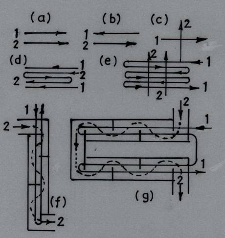
Fig. 25.1 Typical arrangements of fluid flow in heat exchangers
The four pairs of curves plotted characterize the temperature trends of both liquids as they flow along the heating surface, depending on whether the flow is parallel or counter flow, and on whether W1 is larger or smaller than W2. In the figures the heating surface F is plotted along the abscissa and the temperature of the working fluids along the ordinate. The graphs show that the biggest change in the temperature t' – t" = δt occurs in the fluid possessing the smaller water equivalent of the two considered fluids (Fig. 25.2).
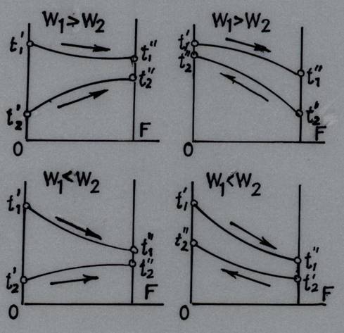
Fig. 25.2 Variation in fluid temperature in parallel-flow & counter flow heat exchangers
Analyzing the
graphs, we see that in parallel flow the final outlet temperature of the cold
fluid ![]() is
always less than the outlet temperature
is
always less than the outlet temperature ![]() of
the hot fluid. On the other hand, in counter flow the outlet temperature
of
the hot fluid. On the other hand, in counter flow the outlet temperature ![]() of
the cold fluid may exceed the outlet temperature
of
the cold fluid may exceed the outlet temperature ![]() of
the hot fluid. Hence, a cold fluid of one and the same inlet temperature may be
heated in counter flow to a higher temperature than in the case of a parallel
flow arrangement.
of
the hot fluid. Hence, a cold fluid of one and the same inlet temperature may be
heated in counter flow to a higher temperature than in the case of a parallel
flow arrangement.
In parallel flow, the temperature difference along the heating surface, changes to a greater extent than in counter flow. At the same time the temperature difference in counter flow is larger than in a parallel-flow arrangement, and because of this factor alone a counter flow heat exchanger is more compact. If, however, the temperature of even one of the working fluids is constant, the mean temperature difference is one and the same, notwithstanding the flow arrangement. This is exactly what happens in the case of boiling liquids and condensing vapours or in the case where the rate of flow of one of the working liquids is so high that its temperature changes very little.
Having examined
the general equations pertaining to the design of heat-exchange apparatuses and
sized up the temperature duty of heat-exchange equipment, let us now proceed to
a more detailed investigation of the values of equation.