Module 5. Heat exchangers
Lesson 27
PARALLEL FLOW, COUNTER FLOW
27.1 Parallel Flow
It has been shown above that the change in the temperature difference follows the exponential law
Δt” = Δt’ e-mkF
Knowing that
![]()
And that at the end of the
heating surface Δt” = ![]() , we substitute these values
, we substitute these values
![]()
This equation, however, shows only the temperature differences. It may be used to determine the individual outlet temperatures by subtracting both members of the equation from unity:
![]()
![]()
![]()
![]()
Inserting this value into the left side of equation, we obtain
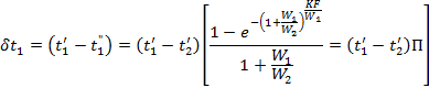
The latter equation shows
that the change in the temperature of the hot fluid δt1 is equal to a certain function Π of the initial temperature
difference ![]() and this fraction depends
only on the two dimensionless terms
and this fraction depends
only on the two dimensionless terms ![]() and
and ![]() .
.
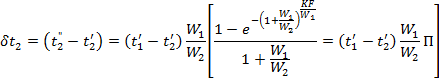
Processing in a similar way, we may derive the expression characterizing the change in the temperature of the cold fluid from formula
Having determined the variation in the temperature of the working fluids and knowing their inlet temperatures, it is easy to determine the final outlet temperatures:
![]()
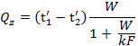
The rate of heat transfer is determined by multiplying the water equivalent of the considered fluid by its change in temperature:
![]()
The function ![]() is
plotted in Fig. 27.1.
is
plotted in Fig. 27.1.
Example
2. Consider a water cooler with a heating surface F = 8 m2.
Determine the outlet temperatures of the fluids and the hourly rate of heat
transfer Q for the following given data: V1 = 0.25 m3/hr,
γ1 = 1,100 kg/m3, cp1 = 0.727 kcal/kg-°C
and ![]() =
120°C. 1,000 l of cooling water a temperature
=
120°C. 1,000 l of cooling water a temperature ![]() = 10°C are
available per hour. Besides, it is known that the overall heat transfer
coefficient k = 30 kcal/m2-hr-°C.
= 10°C are
available per hour. Besides, it is known that the overall heat transfer
coefficient k = 30 kcal/m2-hr-°C.
W1 = 0.25 X 1,100 X 0.727 = 200 kcal/hr-°C.
W2 = 1 X 1000 X 1 = 1,000 kcal/hr-°C.
![]()
The value of the function π is read off the graph (refer Fig. 27.1)
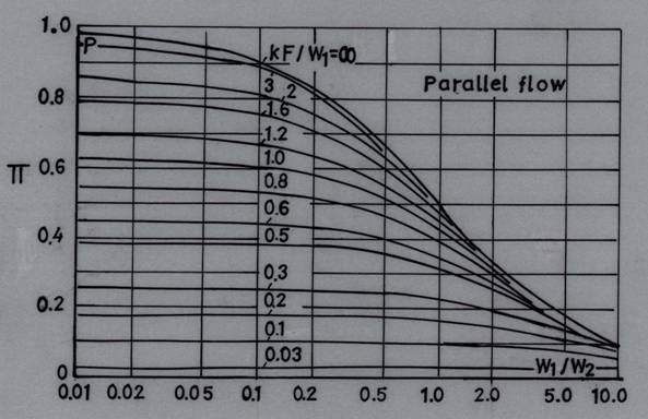
Fig.
27.1 ![]() -- auxiliary function used to calculate outlet
temperature in parallel flow heat exchangers
-- auxiliary function used to calculate outlet
temperature in parallel flow heat exchangers
![]()
The change (drop) in the hot fluid temperature is equal to
![]()
Hence the outlet temperature of the hot fluid is equal to
![]()
The amount of heat transferred per hour is determined by the expression):
![]()
The change in the temperature
of the cold fluid is determined by equation), but it may also be found from the
relationship Q = W2 ![]() , from which
, from which
![]() and
and ![]() .
.
27.2 Counter Flow
Calculation formulas for a counter flow arrangement are derived in the same way as for parallel flow. The final calculation formulas assume the following form:
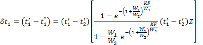
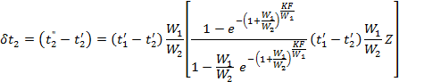
![]()
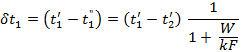
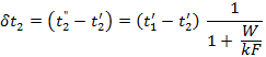
In a particular case where
![]() the formulas acquire the following form:
the formulas acquire the following form:
The function ![]() is
used to calculate outlet temperature in counter flow heat exchanger (refer Fig.
27.2).
is
used to calculate outlet temperature in counter flow heat exchanger (refer Fig.
27.2).
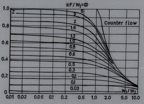
Fig. 27.2 ![]() --
auxiliary function used to calculate outlet
temperature in counter flow heat exchangers
--
auxiliary function used to calculate outlet
temperature in counter flow heat exchangers
If the above formulas are
used to calculate the temperatures of the working fluids and the amounts of
heat transferred intermediate points of the heating surface, F is replaced by Fx; this is done only in
the numerator and the value of the whole surface F is left in the denominator.