Module 5. Transducers
Lesson 17
Electrical Transducers: Capacitive transducers
17.1 Capacitive Transducers
A capacitor consists of two conductors (plates) that are electrically isolated from one another by a nonconductor (dielectric). When the two conductors are at different potentials (voltages), the system is capable of storing an electric charge. The storage capability of a capacitor is measured in farads.The principle of operation of capacitive transducers is based upon the equation for capacitance of a parallel plate capacitor as shown in Fig.17.1
![]()
Where, A = Overlapping area of plates; m2,
d = Distance between two plates; m,
e = Permittivity (dielectric constant); F/m.
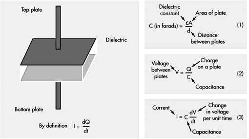
Fig.17.1 Parallel plate capacitor
The capacitance is measured with a bridge circuits. The output impedance ‘Z’ of a capacitive transducer is:
Z = 1/2πfC
Where: Z = Impedance
f = frequency, 50 Hz.
C = capacitance
In general, the output impedance of a capacitive transducer is high. This fact calls for a careful design of the output circuitry. The capacitive transducers work on the principle of change in capacitance of the capacitor. This change in capacitance could be caused by change in overlapping area ‘A’ of the plates, change in the distance ‘d’ between the plates and change in dielectric constant ‘ e’.
In most of the cases the above changes are caused by the physical variables, such as, displacement, force or pressure. Variation in capacitance is also there when the dielectric medium between the plates changes, as in the case of measurement of liquid or gas levels. Therefore, the capacitive transducers are commonly used for measurement of linear displacement, by employing the following effects as shown in Fig. 17.2 and 17.3.
i) Change in capacitance due to change in overlapping area of plates.
ii) Change in capacitance due to change in distance between the two plates.
iii) Change in capacitance due to change in dielectric between the two plates
Fig. 17.2 Variable capacitive transducer varies; (a) area of overlap, (b) distance between plates, (c) amount of dielectric between plates
Fig. 17.3 Differential capacitive transducer varies capacitance ratio by changing: (a) area of overlap, (b) distance between plates, (c) dielectric between plates
As may be seen in Fig.17.3, all of the differential devices have three wire connections rather than two: one wire for each of the ‘end’ plates and one for the ‘common’ plate. As the capacitance between one of the ‘end’ plates and the ‘common’ plate changes, the capacitance between the other ‘end’ plate and the ‘common’ plate also changes in the opposite direction.
a) Transducers Using Change in Area of Plates
Examining the equation for capacitance, it is found that the capacitance is directly proportional to the area, A of the plates. Thus, the capacitance changes linearly with change in area of plates. Hence this type of capacitive transducer is useful for measurement of moderate to large displacements say from 1 mm to several cm. The area changes linearly with displacement and also the capacitance.
For a parallel plate capacitor, the capacitance is:
![]()
Where, l = length of overlapping part of plates; m, and
w = width of overlapping part of plates; m.
![]()
The sensitivity is constant and therefore there is linear relationship between capacitance and displacement.
This type of a capacitive transducer is suitable for measurement of linear displacement ranging from 1 to 10 cm. The accuracy is as high as 0.005%.
b) Transducers Using Change in Distance between Plates
Fig. 17.2(b) shows the basic form of a capacitive transducer employing change in distance between the two plates to cause the change in capacitance. One plate is fixed and the displacement to be measured is applied to the other plate which is movable. Since, the capacitance, C, varies inversely as the distance d, between the plates the response of this transducer is not linear. Thus this transducer is useful only for measurement of extremely small displacements.
![]()
Thus the sensitivity of this type of transducer is not constant but varies over the range of the transducer. The relationship between variations of capacitance with variation of distance between plates is hyperbolic and is only approximately linear over a small range of displacement. The linearity can be closely approximated by use of a piece of dielectric material like mica having a high dielectric constant, such as, a thin piece of mica.
c) Transducers Using Change in dielectric constant between Plates
If the area (A) of and the distance (d) between the plates of a capacitor remain constant, capacitance will vary only as a function of the dielectric constant (e) of the substance filling the gap between the plates. If the space between the plates of a capacitor is filled with an insulator, the capacitance of the capacitor will change compared to the situation in which there is vacuum between the plates. The change in the capacitance is caused by a change in the electric field between the plates.
The value of dielectric constant is initially set by design in the choice of dielectric material used to make the capacitor. Many factors will cause the ‘e’ to change, and this change in ‘e’will vary for different materials. The major factors that will cause a change in ‘e’ are moisture, voltage, frequency, and temperature. The dielectric constant of a process material can change due to variations in temperature, moisture, humidity, material bulk density, and particle size etc. The ‘e’ in the basic formula is the effective dielectric constant of the total ‘space’ between the electrodes. This space may consist of the dielectric material, air, and even moisture, if present. The figure 17.4 shows that how in a capacitor the position of the dielectric is varied to vary the capacitance. Physical variables, such as, displacement, force or pressure can cause the movement of dielectric material in the capacitor plates, resulting in changes in the effective dielectric constant, which in turn will change the capacitance.
Fig.17.4 Change in capacitance due to movement of dielectric between plates
The major advantages of capacitive transducers are that they require extremely small forces to operate them and hence are very useful for use in small systems. They are extremely sensitive and require small power to operate them. Owing to their good frequency response they are very useful for dynamic studies.
The disadvantages of capacitive transducers include their non-linear behaviour on account of edge effects and the effects of stray capacitances especially when the transducers have a low value of capacitance. Therefore guard rings must be used to eliminate this effect. The metallic parts of the capacitive transducers must be insulated from each other. In order to reduce the effects of stray capacitances, the frames must be earthed.
Capacitive transducers can be used for measurement of both linear and angular displacements. The capacitive transducers are highly sensitive and can be used for measurement of extremely small displacements down to the order of molecular dimensions, i.e., 0.1x10⁻⁶ mm. On the other hand, they can be used for measurement of large displacements up to about 30 m as in aeroplane altimeters. The change in area method is used for measurement of displacements ranging from 10 to 100 mm. Capacitive transducers can be used for the measurement of force and pressure. The force and pressure to be measured are first converted to displacement which causes a change of capacitance. Capacitive transducers can also be used directly as pressure transducers in all those cases where the dielectric constant of a medium changes with pressure. They can be used for measurement of humidity in gases and moisture content in soil / food products etc.