Module 5. Transducers
Lesson 18
Electrical Transducers: INDUCTIVE TRANSDUCERS
18.1 Inductance
Inductance is the ability of an inductor
to store energy in a magnetic field. Inductors generate an opposing voltage
proportional to the rate of change in current in a circuit. Inductance is
caused by the magnetic field generated by electric currents. It is typified by
the behavior of a coil of wire in resisting any change of electric current
through the coil. Arising from Faraday’s law, the inductance L may be defined
in terms of the emf generated to oppose a given change in current. The
quantitative definition of the self inductance L of an electrical circuit in SI
units (Webbers per ampere, known as henries) is:
![]()
Where:
v = voltage in volts
i = current in amperes.
This property can be of two types, the self inductance and the mutual inductance. Self-inductance, or simply inductance, is the property of a circuit whereby a change in current causes a change in voltage in the same circuit. When one circuit induces current flow in a second nearby circuit, it is known as mutual-inductance. The self-inductance, L, of a circuit component determines the magnitude of the electromagnetic force (emf) induced in it as a result of a given rate of change of the current through the component. Similarly, the mutual inductance, M, of two components, one in each of two separate but closely located circuits, determines the emf that each may induce in the other for a given current change. The phenomenon of mutual induction is used as the mechanism by which transformer work.
The schematic symbol of inductance and the air-coiled solenoid producing self inductance is shown in Fig. 18.1. Solenoid is a long straight coil of wire and can be used to generate a nearly uniform magnetic field similar to that of a bar magnet. The magnetic field can be greatly strengthened by the addition of an iron core. Such cores are typical in electromagnets. Solenoids have enormous number of practical applications.
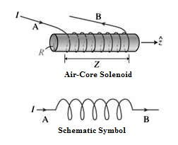
Fig. 18.1 Self-inductance
The emf induced in a coil can be given by the following expression

Where;
N= Number of turns in the coil
Φ = BA = magnetic flux
B = external magnetic field
A = area of coil
The mutual inductance, M, is a measure of the coupling between two inductors. The mutual inductance due the voltage induced in coil 2 due to the current in coil 1 has the following relationship:
M21 = -N1N2P21
Where:
M21 = mutual inductance
N1 = number of turns in coil 1,
N2 = number of turns in coil 2,
P21 = permeance of the space occupied by the flux.
The circuit diagram representation of mutually coupled inductors is shown in Fig. 18.2. The two vertical lines between the inductors indicate a solid core that the wires of the inductor are wrapped around. "n:m" shows the ratio between the number of windings of the left inductor to windings of the right inductor.
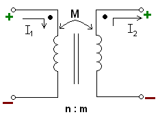
Fig. 18.2 Mutual-inductance
18.2 Inductive Transducers
The inductive transducers work on the principle of the electromagnetic induction. Just as the resistance of the electric conductor depends on number of factors, the induction of the magnetic material depends on a number of variables like the number of turns of the coil on the material, the size of the magnetic material, and the permeability of the flux path. In the inductive transducers the magnetic materials are used in the flux path and there are one or more air gaps. The change in the air gap also results in change in the inductance of the circuit and in most of the inductive transducers it is used for the working of the instrument.
There are two common type inductive transducers: simple inductance type and two-coil mutual inductance type.
18.2.1 Simple
inductance type inductive transducers
In the simple inductance type of the inductive transducers simple single coil is used as the transducer. When the mechanical element whose displacement is to be measured is moved, it changes the permeance of the flux path generated by the circuit, which changes the inductance of the circuit and the corresponding output. The output from the circuit is calibrated directly against the value of the input, thus it directly gives the valve of the parameter to be measured. Fig. 18.3 shows the single coil inductive circuit. Here the magnetic material is connected to the electric circuit and it is excited by the alternating current. At the bottom there is another magnetic material that acts as the armature. As the armature is moved, the air gap between the two magnetic material changes and the permeance of the flux generated by the circuit changes that changes the inductance of the circuit and its output. The output meter directly gives the valve of the input mechanical quantity. This type of transducer can be used in a filpack machine to count the number of packets filled with milk.
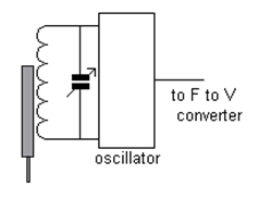
Fig. 18.3 Single coil inductive circuit
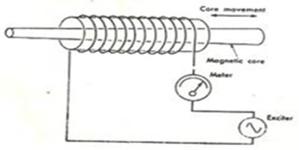
Fig. 18.4 Hollow Coil inductive circuit
In the Fig. 18.4, coil is wound around the round hollow magnetic material and there is magnetic core that moves inside hollow magnetic material. In the above circuits the change in the air gap or the change in the amount of the magnetic material in the circuit can be used to produce the output proportional to the input. In the above arrangements the supply of the current and the output is obtained from the same coil or circuit.
18.2.2 Two-coil mutual inductance
type inductive transducer
In the two coil arrangement there are two different coils. In the first coil the excitation is generated by external source of the power and in the second coil the output is obtained. The output is proportional to the mechanical input. As shown in the figure 18.5 below, A is the excitation coil and B is the output coil. The inductance of the output coil changes due to change in position of the armature which is connected to the mechanical element whose motion is to be measured. As the armature position changes, the air gap between the fixed magnetic material and the armature changes.
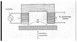
Fig. 18.5 Two-Coil mutual inductance type
inductive transducer
18.3 Linear Variable Differential Transformer (LVDT)
The linear variable differential transformer (LVDT) is the most widely used inductive transducer to translate linear motion into electrical signal.
18.3.1 Construction
A differential transformer consists of a primary winding and two secondary windings. The windings are arranged concentrically and next to each other. They are wound over a hollow bobbin which is usually of a non-magnetic and insulating material. A ferro-magnetic core (armature) in the shape of a rod of cylinder is attached to the transducer’s sensing shaft. The core slides freely within the hollow portion of the bobbin. In the simplex winding configuration, the linear variable displacement transformer LVDT is shown in Fig.18.6. There is one primary and two secondary windings. The secondaries are connected so their outputs are opposite. If an AC excitation is applied across the primary winding then voltages are induced in the secondaries. A movable core varies the coupling between it and the two secondary windings. When the core is in the centre position, the coupling to the secondary coils is equal. As the core moves away from the centre position, the coupling to one secondary becomes more and hence its output voltage increases, while the coupling and the output voltage of the other secondary decreases.
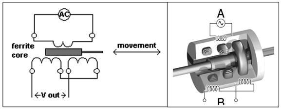
Fig. 18.6 Linear variable differential transformer
18.3.2 Working principle
Any physical displacement of the core causes the voltage of one secondary winding to increase while simultaneously, reducing the voltage in the other secondary winding. The difference of the two voltages appears across the output terminals of the transducer and gives a measure of the physical position of the core and hence the displacement.
When the core is in the neutral or zero position, voltages induced in the secondary windings are equal and opposite and cancel out. The net output is negligible. As the core is moved in one direction from the null position, then there will be more voltage in one secondary than the other. The voltages will not cancel out and there will be an AC signal at the output proportional to the distance the core has moved. The differential voltage, i.e., the difference of the secondary voltages, will increase while maintaining an in-phase relationship with the voltage from the input source. In the other direction from the null position, the differential voltage will again increase, but will be 180°C out of phase with the voltage from the input source. Using a phase detector circuit it is also possible to indicate the direction the core has moved. By comparing the magnitude and phase of the output (differential) voltage with the input source, the amount and direction of movement of the core and hence of displacement may be determined. Variation of output voltage with core position is shown in Fig.18.7.

Fig. 18.7 Variation of output voltage in LVDT with core position
The output voltage of these transducers is practically linear for displacement up to 5 mm. The transducer has infinite resolution and a high sensitivity. It is simple, light in weight, and easy to align and maintain. These transducers can usually tolerate a high degree of shock and vibration without any adverse effects. In addition to this they have low hysteresis and hence repeatability is excellent under all conditions.
The disadvantages of LVDT include their relatively large displacements are requirement for appreciable differential output. They are sensitive to stray magnetic fields but this can be overcome by providing appropriate shielding. Temperature affects the performance of the transducer.
18.3.3 Numerical
1. The output of an LVDT is connected to a 10 V voltmeter through an amplifier with a gain of 250. The voltmeter scale has 100 divisions and the scale can be read up to 1/5th of a division. An output of 2 mV appears across the terminals of the LVDT, when core is displaced through a 0.5 mm. Determine the following:
i) Sensitivity of the measuring system
ii) Resolution of instrument
Solution
Given that
The output voltage of LVDT: V0 = 2 mV
Displacement = 0.5 mm
![]()
Sensitivity of LVDT = Sensitivity of the measuring system =
Amplification factor x Sensitivity of LVDT
= 250 x 4 mV/mm = 1000 mV/mm or 1 V/mm.
Full-scale of voltmeter = 0 – 10 V
No. of divisions on voltmeter scale = 100
1 Scale division = 10 / 100 = 0.10 V or 100 mV
Minimum voltage that can be read on voltmeter = ![]()
![]()