Module 5. Transducers
Lesson 19
MEASUREMENT OF PRESSURE – I
19.1 Introduction
Pressure measurement is one of the most common of all measurements made on systems. Pressure along with flow measurements is extensively used in industry, laboratories and many other fields for a wide variety of reasons. Pressure measurements are concerned not only with determination of force per unit area but are also involved in many liquid level, density, flow and temperature measurements.
19.2 Pressure
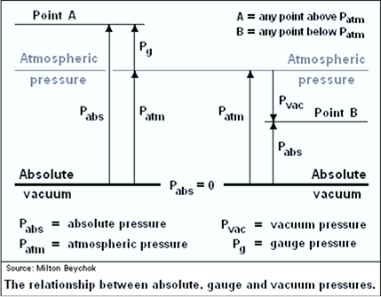
Pressure is the force per unit area exerted by a fluid on the surface of the container. Pressure measurements, are usually made relative to some reference. Everyday pressure measurements, such as, the pressure in a car tire, are usually made relative to ambient air pressure. In other cases measurements are made relative to a vacuum or to some other ad hoc reference. When distinguishing between these zero references, the following terms are used:
i) Atmospheric pressure
The pressure due to air surrounding the earth’s surface is called as atmospheric pressure.
ii) Absolute pressure
It is known that pressure is force per unit area when the interaction of fluid particles among themselves is zero, a zero pressure intensity will occur. This is possible only when the population of molecules is negligibly small which means perfect vacuum. Hence the pressure intensity measured from a state of prefect vacuum is called as absolute pressure. So it is equal to gauge pressure plus atmospheric pressure
iii) Gauge Pressure
A pressure measuring instrument generally measures the difference between the unknown pressure (P) and the atmospheric pressure (Pata). When the unknown pressure (P) is greater than the atmospheric pressure (Patm), the pressure measured by the instrument is called as the gauge pressure. In Gauge pressure is zero referenced against ambient air pressure, so it is equal to absolute pressure minus atmospheric pressure. Negative signs are usually omitted.
iv) Vacuum pressure
A Pressure measuring instrument generally measures the difference between the unknown pressure (P) and the atmospheric pressure (Patm). When the atmospheric pressure (Patm) is greater than the unknown pressure (P), the pressure measured by the instrument is called as the vacuum pressure
Atmospheric pressure is typically about 100 kPa at sea level, but is variable with altitude and weather. If the absolute pressure of a fluid stays constant, the gauge pressure of the same fluid will vary as atmospheric pressure changes. Use of the atmosphere as reference is usually signified by a (g) after the pressure unit e.g. 30 psi g, which means that the pressure measured is the total pressure minus atmospheric pressure.
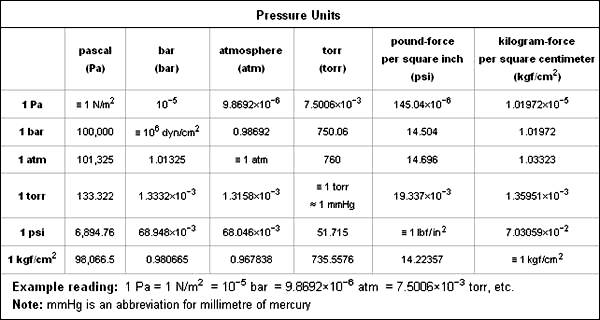
Following table presents various units of pressure measurement and their equivalents to each other:
Table 19.1 Units of pressure measurement
v) Static and Dynamic Pressure
Static pressure is uniform in all directions, so pressure measurements are independent of direction in an immovable (static) fluid. Flow, however, applies additional pressure on surfaces perpendicular to the flow direction, while having little impact on surfaces parallel to the flow direction. This directional component of pressure in a moving (dynamic) fluid is called dynamic pressure. An instrument facing the flow direction measures the sum of the static and dynamic pressures; this measurement is called the total pressure or stagnation pressure. Since dynamic pressure is referenced to static pressure, it is neither gauge nor absolute; it is a differential pressure. While static gauge pressure is of primary importance to determining net loads on pipe walls, dynamic pressure is used to measure flow rates and airspeed. Dynamic pressure can be measured by taking the differential pressure between instruments parallel and perpendicular to the flow. Pitot-static tubes, for example perform this measurement on airplanes to determine airspeed. The presence of the measuring instrument inevitably acts to divert flow and create turbulence, so its shape is critical to accuracy and the calibration curves are often non-linear.
In processing industries the measurement of pressure is required to maintain safe operating conditions, to help control a process and to provide test data. In industrial applications the pressure is usually measured by means of indicating gauges or recorders. These instruments could be mechanical, electro-mechanical or electronic in operation. The mechanical instruments include those instruments in which pressure measurement is made by balancing unknown force with a known force and those instruments which employ quantitative deformation of air elastic member for pressure measurement. The electro-mechanical instruments usually employ a mechanical means for detecting the pressure and the electrical means for indicating or recording the detected pressure. The electronic pressure measuring instruments normally depend upon some physical change that can be detected and indicated or recorded electronically. In this text, the description will be limited only to the elastic deformation elements and transducers employed in mechanical or electro-mechanical measurement of pressure.
19.3 Measurement of Pressure
Many instruments have been invented to measure pressure, with different advantages and disadvantages. Pressure range, sensitivity, dynamic response and cost all vary by several orders of magnitude from one instrument design to the next. The oldest type is the liquid column (a vertical tube filled with mercury) manometer. Following table gives the instruments which are used in various situations:
Table 19.2
|
Type of pressure to be measured |
Pressure Measuring instrument to be used |
|
Low pressure |
Manometer |
|
High and medium pressure |
Bourdon tube pressure gauge. Diaphragm gauge. Bellows Gauges. |
|
Low vacuum and ultra high vacuum |
McLeod vacuum gauge Thermal conductivity gauges. Ionisation gauges. |
|
Very high pressures |
Bourdon tube pressure gauge. Diaphragm gauge. Bulk modulus pressure gauge. |
19.4 Manometer Gauges
The difference in fluid height in a liquid column manometer is proportional to the pressure difference. Liquid column gauges consist of a vertical column of liquid in a tube whose ends are exposed to different pressures. The column will rise or fall until its weight is in equilibrium with the pressure differential between the two ends of the tube. A very simple version is a U-shaped tube manometer (Fig. 19.1) is half-full of liquid, one side of which is connected to the region of interest while the reference pressure, which could be the atmospheric pressure or a vacuum, is applied to the other. The difference in liquid level represents the applied pressure.
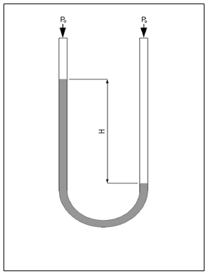
Fig. 19.1 U-Shaped tube manometer
The pressure (P) exerted by a column of fluid of height h and density ρ is given by the hydrostatic pressure equation
P = hgρ.
Therefore the pressure difference between the applied pressure Pa and the reference pressure P0 in a U-tube manometer can be found by solving
Pa − P0 = hgρ.
In other words, since the liquid is static, the pressure on either end of the liquid shown in the figure 19.1 must be balanced and so
Pa = P0 + hgρ.
If the fluid being measured is significantly dense, hydrostatic corrections may have to be made for the height between the moving surface of the manometer working fluid and the location where the pressure measurement is desired.
Although any fluid can be used in the manometer, mercury is preferred for its high density (13.534 g/cm3) and low vapour pressure. For low pressure differences well above the vapour pressure of water, water is commonly used and “mm or inches of water" is a common pressure unit. Liquid-column pressure gauges are independent of the type of gas being measured and have a highly linear calibration. However, they have poor dynamic response. When measuring vacuum, the working liquid may evaporate and contaminate the vacuum if its vapor pressure is too high. When measuring liquid pressure, a loop filled with gas or a light fluid can isolate the liquids to prevent them from mixing. This may not be required when mercury is used as the manometer fluid to measure differential pressure of a fluid such as water. Simple hydrostatic gauges can measure pressures ranging from a few Torr (a few 100 Pa) to a few atmospheres. (Approximately 1,000,000 Pa)
A single-limb liquid-column manometer has a larger reservoir instead of one side of the U-tube and has a scale beside the narrower column. The column may be inclined to further amplify the liquid movement.
Based on the use and structure following type of manometers are used
1. Simple Manometer
2. Micro manometer
3. Differential manometer
4. Inverted differential manometer
19.5 Bourdon Tube
It is most widely used as a pressure sensing element. It consists of a narrow bore tube of elliptical cross-section, sealed at one end. The pressure is applied at the other end which is open and fixed. The tube is formed into a curve, a flat spiral or a helix. When the pressure is applied, the effect of the forces is to straighten it so that the closed end is displaced. Fig.19.2 illustrates a C bourdon tube as used in direct indicating gauge which usually has an arc of 250°. The process pressure is connected to the fixed socket end of the tube while the tip end is sealed. Because of the difference between inside and outside radii, the bourdon tube presents different areas to pressure, which causes the tube to tend to straighten when pressure is applied. The resulting tip-motion is non-linear because less motion results from each increment of additional pressure. This non-linear motion has to be converted to linear rotational pointer response. This is done mechanically by means of a geared sector and pinion movement as shown in figure. The tip motion is transferred to the tail of the movement sector by the connector link. The angle between the connecting link and the sector tail is called the ‘travelling angle’. This angle changes with tip movement in a non-linear fashion and so the movement of the pinion and, therefore, pointer is linear.
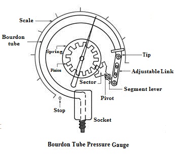
Fig. 19.2 Bourdon pressure gauge
Frequently used bourdon tube materials include bronze, alloy and stainless steel. These elements are not ideally suited for low pressure, vacuum or compound measurements because the spring gradient of bourdon tube is too low.
The advantages of Bourdon tube pressure gauges are that they give accurate results. Bourdon tubes are simple in construction and their cost is low. They can be modified to give electrical outputs. They are safe even for high pressure measurement and the accuracy is high especially at high pressures. The Bourdon gauge coupled with a S.S, capsule type sensing bulb is used in milk homogenizer.
The Bourdon tube pressure gauges have some limitations also. They respond slowly to changes in pressure. They are subjected to hysteresis and are sensitive to shocks and vibrations. As the displacement of the free end of the bourdon tube is low, it requires amplification. More over, they cannot be used for precision measurement.
19.6 Elastic Diaphragm Gauges
As already discussed that when an elastic transducer, such as diaphragm, is subjected to a pressure, it deflects. This deflection is proportional to the applied pressure when calibrated. Elastic diaphragm gauges are built on this principle. The main part of the diaphragm gauge is a thin circular plate which is firmly fixed around its edges. The diaphragm may either be flat, dish, corrugated or corrugated as shown in Fig 19.3.
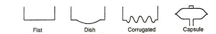
Fig. 19.3 Diaphragm elements
The top portion of the diaphragm is fixed with a bourdon tube of negligible weight. This bourdon tube is in-turn connected to a link – sector – pinion arrangement using mechanical means for displacement magnification. A pointer is connected to the pinion which makes it sweep over a pressure calibrated scale. The bottom side of the diaphragm is exposed to the pressure which is to be measured. Due to the applied pressure, the diaphragm deforms. That is the diaphragm tends to move upwards. This deformation of the diaphragm is proportional to the applied pressure. In a mechanical system, this deformation is magnified by the link – sector – pinion arrangement. That is, the linear displacement of the diaphragm is converted to a magnified rotary motion of the pinion. When the pinion rotates, it makes the pointer attached to it to assume a new position on the pressure calibrated scale which becomes a measure of the applied pressure. As the top side of the diaphragm is usually subjected to the atmospheric pressure, generally less than the applied pressure, the elastic diaphragm gauges usually read gauge pressure.
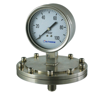
Fig. 19.4 Elastic
diaphragm gauges
If the displacement is sensed by a secondary transducer such as a parallel plate capacitor, its movable plate is connected to the external circuit. In such arrangement the movable plate moves upwards, thus reducing the gap between the plates. This makes the capacitance of the capacitor becomes a measure of the applied pressure.