Module 5. Transducers
Lesson 20
MEASUREMENT OF PRESSURE – II
20.1 Dead Weight Tester
The dead weight tester is basically a pressure producing and pressure measuring device. It is used to calibrate pressure gauges. The dead weight tester apparatus consists of a piston – cylinder combination fitted above the chamber as shown in Fig. 20.1.The chamber below the cylinder is filled with oil. The top portion of the piston is attached with a platform to carry weights. A plunger with a handle is provided to vary the pressure of oil in the chamber. The pressure gauge to be tested is fitted at an appropriate place as shown in the Fig. 20.1.
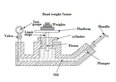
Fig. 20.1 Dead weight tester
To calibrate a pressure gauge, an accurately known sample of pressure is introduced to the gauge under test and then the response of the gauge is observed. In order to create this accurately known pressure, the valve of the apparatus is closed and a known weight is placed on the platform above the piston. By operating the plunger, fluid pressure is applied to the other side of the piston until the force developed is enough to lift the piston-weight combination. When this happens, the piston weight combination floats freely within the cylinder between limit stops. In this condition of equilibrium, the pressure force of fluid is balanced against the gravitational force of the weights plus the friction drag on the piston. The pressure which is caused due to the weights placed on the platform is calculated using the area of the piston. Now the pressure gauge to be calibrated is fitted at an appropriate place on the dead weight tester. Now the valve in the apparatus is opened so that the fluid pressure P is transmitted to the gauge, which makes the gauge indicate a pressure value. This pressure value shown by the gauge should be equal to the known input pressure P. If the gauge indicates some other value then the gauge is calibrated, adjusting the pressure on the gauge so that it reads a value equal to input pressure. Gauge tester is used to calibrate all kinds of pressure gauges and a wide range of pressure measuring devices. It is simple in construction and easy to use.
20.2 McLeod Vacuum Gauge
The McLeod Gauge is used to measure vacuum pressure. It also serves as a reference standard to calibrate other low pressure gauges. The components of McLeod gauge include a reference column with reference capillary tube. The reference capillary tube has a point called zero reference point. This reference column is connected to a bulb and measuring capillary and the place of connection of the bulb with reference column is called as cut off point. It is called so because if the mercury level is raised above this point, it will cut off the entry of the applied pressure to the bulb and measuring capillary. Below the reference column and the bulb, there is a mercury reservoir operated by a piston.
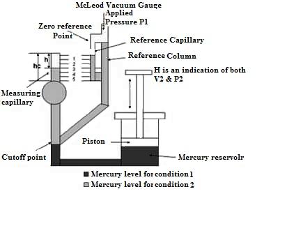
Fig. 20.2 McLeod vacuum gauge
The pressure to be measured (P1) is applied to the top of the reference column of the McLeod Gauge as shown in Fig. 20.2. The mercury level in the gauge is raised by operating the piston to fill the volume as shown by the dark shade in the diagram. When the applied pressure fills the bulb and the capillary, again the piston is operated so that the mercury level in the gauge increases. When the mercury level reaches the cut-off point, a known volume of gas (V1) is trapped in the bulb and measuring capillary tube. The mercury level is further raised by operating the piston so the trapped gas in the bulb and measuring capillary tube is compressed. This is done until the mercury level reaches the “Zero reference Point” marked on the reference capillary. In this condition, the volume of the gas in the measuring capillary tube is read directly by a scale besides it. That is, the difference in height ‘H’ of the measuring capillary and the reference capillary becomes a measure of the volume (V2) and pressure (P2) of the trapped gas. Now as V1, V2, and P2 are known, the applied pressure P1 can be calculated using Boyle’s Law given by:
P1V1 = P2 V2
The working of McLeod Gauge is independent of the gas composition. A linear relationship exists between the applied pressure and height and there is no need to apply corrections to the readings. The limitations are that the gas whose pressure is to be measured should obey the Boyle’s law and the presence of vapours in the gauge affects the performance.
20.3 Pirani Gauge
The Pirani gauge consists of a metal wire open to the pressure being measured. The wire is heated by a current flowing through it and cooled by the gas surrounding it. If the gas pressure is reduced, the cooling effect will decrease; hence the equilibrium temperature of the wire will increase. The resistance of the wire is a function of its temperature and by measuring the voltage across the wire and the current flowing through it, the resistance can be determined and so the gas pressure is evaluated.

Fig. 20.3 Pirani gauge
Fig. 20.3 shows a Pirani gauge withtwo platinum alloy filaments which act as resistances in two arms of a Wheatstone bridge. One filament is the reference filament and the other is the measurement filament. The reference filament is immersed in a fixed-gas pressure, while the measurement filament is exposed to the system gas. A current through the bridge heats both filaments. Gas molecules hit the heated filaments and conduct away some of the heat. If the gas pressure around the measurement filament is not identical to that around the reference filament, the bridge is unbalanced and the degree of unbalance is a measure of the pressure. The unbalance is adjusted and the current needed to bring about balance is used as a measure of the pressure.
20.4 Ionization Gauge
These gauges are the most sensitive gauges for measuring very low pressures or high vacuum. The principle of operation of these gauges sensing pressure of gas by measuring the electrical ions produced when the gas is bombarded with electrons. Fewer ions will be produced by lower density gases. The electrons are generated by thermo ionic emission. These electrons collide with gas atoms and generate positive ions. The ions are attracted to a suitably biased electrode known as the collector. The current in the collector is proportional to the rate of ionization, which is a function of the pressure in the system. Hence, measuring the collector current gives the gas pressure.
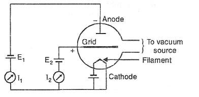
Fig. 20.4 Hot filament ionization gauge
The ionization gauges are of two types, the hot cathode ionization gauges and the cold cathode ionization gauges. In hot cathode (Fig. 20.4) version an electrically heated filament produces an electron beam. The electrons travel through the gauge and ionize gas molecules around them. The resulting ions are collected at a negative electrode. The current depends on the number of ions, which depends on the pressure in the gauge. The working of cold cathode gauge is also same with the only difference in the production of electrons which are produced in the discharge of a high voltage.
20.5 Thermal Conductivity Vacuum Gauge
The thermal conductivity vacuum gauge works on the principle that at low pressure the thermal conductivity of a gas is a function of pressure. The Fig. 20.5 shows the basic elements of a thermocouple vacuum gauge. It consists of a linear element which is heated by a known current source and is contact with a thermocouple attached to its centre. The heater element together with the thermocouple is enclosed in a glass enclosure. The vacuum system to be evaluated is connected to this enclosure. The heater element is supplied with a constant electrical energy. The temperature of the heating element is a function of heat loss to the surrounding gas, which in turn is a function of thermal conductivity of gas that is dependent on the pressure of the gas. The temperature is measured by the thermocouple and is calibrated to read the pressure of the gas.
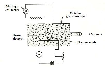
Fig. 20.5 Thermal conductivity vacuum gauge
This gauge is inexpensive and rugged in construction. It provides a convenient and continuous reading with a possibility of remote display. It however needs an individual and frequent calibration for different gases.