Module 5. Transducers
Lesson 22
MEASUREMENT OF TEMPERATURE – I
22.1 Introduction
Temperature is a physical property of matter that quantitatively expresses the hotness or coldness of an object or a process. The objects of low temperature are cold, while various degrees of higher temperatures are referred to as warm or hot. For most temperature measurements the Celsius scale (°C) is used. The freezing point of water in the Celsius scale is 0°C and boiling point is 100°C. The Celsius scale has the same incremental scaling as the Kelvin scale, however, the 0°C on Celsius scale is equal to 273.15K. A few countries, most notably The United States, use the Fahrenheit scale for common purposes. On this scale the freezing point of water is 32 °F and the boiling point is 212°F.
Several methods have been developed for measuring temperature. Most of these methods depend upon measuring some physical property of a working material that varies with temperature. One of the most common devices for measuring temperature is the glass thermometer. Other important temperatures measuring transducers are the bimetallic strips, resistance temperature detector, thermocouples, thermistor, pyrometers etc.
22.2 Thermometers
22.2.1 Liquid-in-glass thermometer
This type of thermometer consists of a liquid-filled glass bulb and connecting micro-fine size of capillary tube. The bulb is filled with mercury or some other liquid, which acts as the working fluid. The increase in temperature causes the fluid in the bulb to expand and to contract as the temperature falls. Thus, the temperature can be determined by measuring the volume of the fluid. The differential expansion between the glass and the liquid causes the liquid to rise in the capillary. Such thermometers are usually calibrated so that one can read the temperature simply by observing the level of the fluid in the thermometer.
A variety of liquids, such as mercury, alcohol, toluene and pentene are used in thermometer construction to cover diverse ranges of temperature. These thermometers are available in many configurations, such as, the read out thermometers, the digital readout thermometers and the recording thermometers which uses a pen on a rotating drum to continuously record temperature readings.
22.2.2 Gas filled thermometer
This type of thermometer has a Bourdon tube connected to a hollow bulb by a capillary tube. The system is filled with a gas which is usually nitrogen or helium. The pressure in the system follows the gas law and the indication of temperature is obtained from the Bourdon tube. The temperature-pressure-motion relationship is nearly linear. The effect of atmospheric pressure is minimized by filling the system to a high pressure. These systems are also available with liquid filled designs. In such a system, the volume change of the liquid actuates the Bourdon tube for temperature indication.
22.2.3 Vapor-pressure thermometer
The construction of such thermometer is same as that of the gas filled thermometer. Only difference is instead of gas pressure they utilize the vapor pressure of certain stable liquids to measure temperature. Since a nonlinear relationship exists between the temperature and the vapor pressure, the motion of the bourdon tube is greater at the upper end of the vapor-pressure curve.
22.3 Bimetallic Thermometers
The bimetallic thermometer is based on the principle that all metals change in their dimension, that is, expand or contract whenever there is a change in temperature. The rate at which this expansion or contraction takes place, depends on the ‘temperature co-efficient of expansion’ of the metal. This temperature coefficient of expansion is different for different metals. This difference in thermal expansion rates is used to produce deflections which are proportional to temperature changes.
A bimetallic strip is thus used to convert a temperature change into mechanical displacement. The device consists of two strips of different metals which expand at different rates as they are heated. Invar is commonly used as the low expansion metal. It is an iron-nickel alloy containing 36% nickel and its co-efficient of thermal expansion is around 1/20th of the other metals. Brass is used as high expansion material. These strips are joined together throughout their length by riveting, brazing or welding so that there is no relative motion between them. The different expansions of both the metals force the flat strip to bend one way if heated, and in the opposite direction if cooled below its initial temperature. The metal with the higher coefficient of thermal expansion is on the outer side of the curve when the strip is heated and on the inner side when cooled. Thus an increase in temperature will result in the deflection of the free end of the strip as shown in the Fig. 22.1. This deflection is linear and can be related to temperature changes.
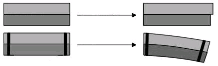
Fig. 22.1 Bimetallic strip
Different common forms of bimetallic sensors include Flat, Spiral or Cantilever, type. Metals used in bimetallic strips are Brass and Nickel-iron alloyed with chromium & manganese as high expansion metal and Invar (alloy of nickel & iron) as low expansion metal. The bimetallic thermometers are simple, robust and inexpensive. Their accuracy is between +or- 2% to 5% of the scale. The only limitation is that when regularly used, the bimetallic may permanently deform, which will introduce errors. They are not recommended for temperature above 400’C. The bimetallic strip is also used in control devices. The spiral strip is used in air conditioning thermostats. A helical strip put inside a SS tube as sensor is used for horizontal milk tanks.
22.4 Resistance Thermometer or Resistance Temperature Detector (RTD)
The electrical resistance of some metals change with change in temperature. Resistance thermometer utilizes this characteristic. With the increase of temperature, the electrical resistance of some metals increases in direct proportion to the rise of temperature, so if the electrical resistance of a wire of known and calibrated material is measured, the temperature of the wire can be determined.
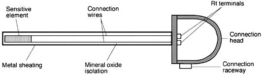
Fig. 22.2 Resistance thermometer
In this type of thermometer, a temperature sensitive resistance element is fabricated in a suitable probe form to insert in a medium whose temperature is to be measured. Resistance elements are generally long, spring like wires enclosed in a metal sheath as shown in Fig. 22.2. The conductors used for resistance thermometer are platinum, nickel of various purities. Platinum is the most commonly used metal for RTD elements due to its chemical inertness, nearly linear and large enough temperature versus resistance relationship and stability. The resistance element is surrounded by a porcelain insulator which prevents short circuit between wire and the metal sheath. Two leads are attached to each side of the platinum wire. When this instrument is placed in a liquid or a gas medium whose temperature is to be measured, the sheath quickly reaches the temperature of the medium. This change in temperature causes the platinum wire inside the sheath to heat or cool, resulting in a proportional change in the wires resistance. This change in resistance can be directly calibrated to indicate the temperature.
Resistance of metal at temperature ‘t’ is given by:
Rt = R0 (1 + α0t)
Where:
Rt = Resistance at t°C
R0 = Resistance at 0°C
α0 = Temperature coefficient of resistance at 0°C
The common configuration of RTD has the platinum resistance element range in length from 1/8" to 3". There are many options. The standard resistance is 100 Ω at 0° C. The most common outside diameter is 1.5 to 12.5 mm. The 316 Stainless steel is commonly used tubing material. RTDs are available in 2, 3 and 4 wire configuration and 3 wire configurations are the most common for industrial applications. Teflon and fiberglass are the standard wire insulation materials. Three wire RTDs normally use a Wheatstone bridge measurement circuit to measure the resistance. Now when sensing element resistance changes, the wheat-stone bridge becomes unbalanced and thus galvanometer will give deflection which can be calibrated to give suitable temperature scale.
Resistance thermometers possess high accuracy of measurement. They have a wide temperature range from – 200 to 650°C. They are fast in response and have good reproducibility. The limitations include their high cost, requirement of a bridge circuit and power supply.
They are widely used in HTST pasteurizer and spray dryers.
22.5 Thermocouples
The working principle of a thermocouple depends on the thermo-electric effect. When two dissimilar metals are joined so as to form a closed circuit, there are two junctions where they meet each other. If one of those junctions is heated, then, a current flows in the circuit which can be detected by a galvanometer. The amount of the current produced depends on the difference in temperature between the two junctions and on the characteristics of the two metals. This was first observed by Seebeck in 1821 and is known as Seebeck effect.
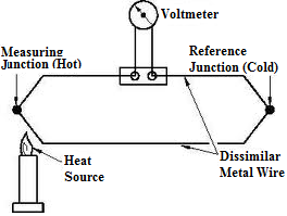
Fig. 22.3 Thermocouple
Instrument based on the above principle is known as thermocouple. Fig. 22.3 shows a thermocouple made from two different kinds of metals. The wires are joined at the ends which form two junctions – a measuring junction and a reference junction. Heating the measuring junction produces a voltage greater than the voltages across the reference junction the difference between two voltages is measured and voltmeter reading is converted to its corresponding temperatures. The conversion table is generally supplied by the thermocouple manufacturers. There are various types of thermocouples which are used in industries, viz. Copper constantan, iron constantan, chromel alumel, platinum rhodium and chromels-constantan.
Thermocouples can be classified in two categories
i) Base metal thermocouples
ii) Rare metal thermocouples
Base-metal thermocouples use the combination of pure metals and alloy of iron, copper and nickel and are used up to 1450 K. These types of thermocouples are more sensitive, cheaper and have nearly linear characteristics. But operating range is low and vulnerable to oxidation. Rare-metal thermocouples use a combination of pure metal and alloys of platinum, tungsten, rhodium, molybdenum etc. which are used for higher temperature measurement up to 2500oC. The characteristics of thermocouples are given in the Table 22.1.
Table 22.1 Characteristics of thermocouples
|
Sr. No. |
Type |
Thermocouple |
Useful temperature range ( oC) |
Sensitivity (μV/oC) |
|
1. 2. 3. 4. 5. 6. |
T J K E R S |
Copper-Constantan Iron-Constantan Chromel-Alumel Chromel-Constantan Platinum-Platinum/13%Rhodium Platinum-Platinum/10%Rhodium |
-180 to 400 -180 to 850 -200 to 1300 -180 to 850 0 to 1600 0 to 1400 |
20-60 50-55 40-55 50-80 5-12 5-12 |
When high sensitivity is required, thermocouples are attached in series. This is known as thermopile.
The thermocouples used in industries consist of a protective well and head across the measuring junction to protect thermocouples from harmful atmospheres, corrosive fluids, mechanical damage and to support the thermocouples to avoid damages in pressurized systems. Thermocouples can be connected in parallel to provide the average temperature in a system. They can also be used to measure the difference between two temperatures. A single thermocouple can be utilized by two separate measuring instruments, with proper precautions. The e.m.f. charts and tables for various thermocouples are available. The thermocouple tables are based upon the reference junction temperature of 0°C, therefore, a direct conversion from the tables can be made only when an ice bath is used at the reference junction. If it is not possible to maintain the reference junction temperature at 0°C a correction factor must be applied to the milli volt values shown in the thermocouple tables.
Thermocouples are cheaper than RTD. They are rugged in construction and can be used for wide temperature range. No external power is required. They are simpler to use than resistance thermometers. There is no need of a bridge circuit. They have extremely wide temperature range from – 270°C to 2800°C. Their electrical output is adaptable to a variety of readout and / or control devices. They can process long transmission distances.
However they have some disadvantages, such as, their instability, low and non-linear output signal. They need to hold reference junction temperatures constant or compensation for any deviations. They require signal amplification for many applications and need expensive accessories for control applications
Example: A T type thermocouple has linear calibration between 0 and 500 oC with emf at maximum temperature (reference temperature oC) equal to 21.5 mV. Determine the correction to be made to the indicated emf, if the cold junction temperature is 25 oC. If the indicated emf is 9.0 mV, determine the temperature of the hot junction.
Solution:
Sensitivity = 2.15 / 500 = 0.043 mV/ oC
E correction = 0.043 x 25 = 1.075 mV
Difference of temperature between hot and cold junction = 9.0/0.043 = 209.30 oC
The reference junction temperature = 25 oC
![]() The hot junction temperature =
209.30+25 = 234.3 oC
The hot junction temperature =
209.30+25 = 234.3 oC