Module 5. Transducers
Lesson 23
MEASUREMENT OF TEMPERATURE – II
23.1 Thermistor
Thermistor or thermal resistor is thermal sensitive resistor. Its resistance changes with temperature. Depending upon the way it responds to temperature, the change in resistance character divides the thermistor into two types. The positive temperature coefficient (PTC) thermistor is that in which resistance of the thermistor increases with the increase in temperature. These thermistors are usually made from Barium, Titanate. The negative temperature coefficient thermistor (NTC) in which, resistance of thermistor decreases with increase in temperature. In broad term a thermistor is semiconductor component that behave as a resistor with usually, negative temperature coefficient of resistance. In some cases, resistance of a thermistor at room temperature may decrease to 5 percent for each one degree Celsius rise in temperature.
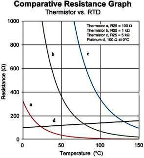
Fig. 23.1 resistance-temperature characteristics of RTD and thermistors
Fig. 23.1 gives the comparison between the changes in resistance due to change in temperature for both the thermistors and the RTD. Positive resistance-temperature correlation in RTD and high negative correlation for thermistors is clearly illustrated. Thermistors are composed of sintered mixture of metallic oxides such as manganese, nickel, cobalt, copper, iron and uranium. They are available in a number of configurations, as shown in Fig. 23.2. Most familiar is the bead type, usually glass coated. They can also be made into washers, discs or rods. Different types of thermistors configurations are shown in the figure below. Thermistors can also be encapsulated in plastic, cemented, and soldered in bolts, encased in glass tubes, needles or a variety of other forms. These assemblies serve to support the sensors, protect against damage to the wires, direct flow across the unit uniformly, permit sealing of conduits or flow lines, and provide for easier handling.

Fig. 23.2 Different types of thermistor configurations
Bead thermistors are the smallest thermistors which are in the form of heads with a diameter of 0.15mm to 1.25mm. This is the most familiar type of thermistor and is usually glass coated. Beads may be sealed in the tips of solid glass rods to form probes. Glass probe have a diameter of about 2.5mm. The probes are used for measuring temperature of liquids.
Thermistors are also made into discs by pressing material under high pressure into cylindrical flat shapes with a diameters ranging from 2.5mm to 25mm. they are mainly used for temperature control. The washer type thermistors are usually long cylindrical units. Leads are attached to the ends of the rods. The advantage of this type is, it produce high resistance under moderate power.
To measure temperature with a thermistor, it is placed in the environment whose temperature is to be measured. As the temperature of the substance or environment increases, the resistance of the thermistor decreases, and vice-versa. This change in thermistor resistance can be detected which will be the measure of the temperature of the substance. Generally, the thermistor is placed as one leg of a wheat-stone bridge circuit. At balanced condition, when there is no change in temperature the galvanometer indicates zero. As the temperature increases or decreases, the resistance of the thermistor also decreases or increases due to which the wheat-stone bridge circuit becomes unbalanced. Thus an electric current flows through the galvanometer which indicates on the calibrated scale. The deflection of the galvanometer can be calibrated as a temperature scale.
All types of thermistors are of small sizes and have fast response. These are most sensitive and are suitable for narrow spans. The thermistor is at least 10 times more sensitive than the platinum resistance element. Since the resistance is a function of absolute temperature, cold junction compensation is not necessary. Due to the large resistance, the contact or lead-wire resistance is considered as negligible as compared to the resistance of thermistors. The cost of thermistors is very low. The major limitations of using thermistors are that they have a highly non-linear resistance-temperature characteristic and the problems of self-heating effects necessitate the use of much lower current levels than those with metallic sensors. The temperature-resistance characteristic of a thermistor is of exponential type and is given by:
![]()
Where, R0 is the resistance at the reference temperature T0 (Kelvin)
R is the resistance at the measured temperature T (Kelvin)
b is the experimentally determined constant for the given thermistor material.
The values of b usually lie between 3000 and 4000 K depending on the formulation or grade.
Example: A thermistor used for temperature measurement has b=3140 K and the resistance at 27°C is 1050 W. If the resistance of the thermistor is measured as 2330 W, find the temperature.
Solution. The resistance-temperature characteristic of the thermistor is given by:
![]()
As per the data given in the statement:
R0 = 1050 W
T0 = 273 + 27 = 300 K
b = 3140 K
R = 2330 W
Taking the logarithm of both sides of equation and rearranging we get,
![]()
![]()
= 3.587 x 10-3
= 278.78 K
23.2 Pyrometers
When temperature to be measured is high and physical contact with the hot body or medium is not possible, pyrometers are used to measure the temperature. Pyrometers are used under conditions where corrosive vapours or liquid could damage the thermocouples, resistance thermometer and Thermistor. The pyrometers also find applications where the temperatures are above the range of thermocouple. There are two types of pyrometers which are commonly used, viz. radiation pyrometers and optical pyrometers.
23.2.1 Radiation pyrometer
The radiation pyrometer measures the heat emitted by a hot object. The radiation pyrometers operate on the principle that the energy radiated from a hot body is a function of its temperature. Basically, thermal radiations are electromagnetic radiation lies in the wavelength region from about 0.1 to 100 micrometer. The energy radiated by the hot body whose temperature is measured is focused by the lens to the detector. The detector is usually a thermocouple and the detector output is given to a PMMC instrument, digital display or recorder.
There are two principles used for the construction of radiation temperature measuring devices. The Total radiation pyrometer is one in which the total radiant energy from a heated body is measured, and the Selective radiation pyrometer in which the radiated energy from the heated body is measured at a given wavelength.
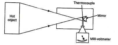
Fig. 23.3 Radiation pyrometer
A total radiation pyrometer is shown in Fig. 23.3. Radiations from hot object is collected and focussed on a thermocouple with the help of a mirror. This increases the thermocouple temperature and generates an emf. The rise in temperature is the function of amount of radiation emitted by the hot object. This instrument has a high speed of response and is primarily used to measure the temperature in the range of 700 to 2000°C. Direct contact is not necessary with the object whose temperature is to be measured.
23.2.2 Optical pyrometer
The principle of temperature measurement by brightness comparison is used in optical pyrometer. A colour variation with the growth in temperature is taken as an index of temperature. The optical pyrometer compares the brightness of image produced by temperature source with that of reference temperature lamp. The current in the lamp is adjusted until the brightness of the lamp is equal to the brightness of the image produced by the temperature source. Since the intensity of light of any wave length depends on the temperature of the radiating object, the current passing through the lamp becomes a measure of the temperature of the temperature source when calibrated. The current in the lamp is adjusted until the brightness of the lamp is equal to the brightness of the image produced by the temperature source. The main parts of an optical pyrometer are shown in the Fig. 23.4.
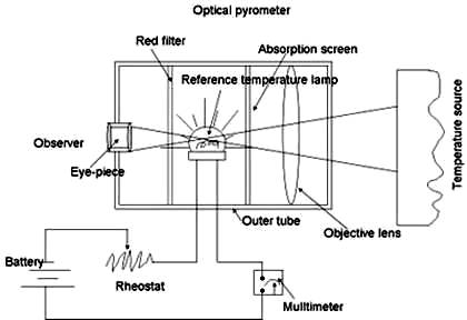
Fig. 23.4 Optical pyrometer
The instrument has an eye piece at one end and an objective lens at the other end. A power source (battery), rheostat and multimeter to measure current are connected to a reference temperature bulb. An absorption screen is placed in between the objective lens and reference temperature lamp. The absorption screen is used to increase the range of the temperature which can be measured by the instrument. The red filter between the eye piece and the lamp allows only a narrow band of wavelength of around 0.65µm.
When a temperature of the source is to be measured, the radiations from the source are focused onto the filament of the reference temperature lamp using the objective lens. The eye piece is adjusted in such a way that the filament of the reference temperature lamp is in sharp focus and the filament is seen super imposed on the image of the temperature source. The lamp current is then controlled. The filament will appear dark as in first image (A) of the Fig. 23.5, if the filament is cooler than the temperature source. The filament will appear bright as in second image (B) of the figure if the filament is hotter than the temperature source. If the filament and temperature source are in the same temperature the filament will disappear (C).

Fig. 23.5 Images of temperature source in Optical pyrometer
Hence the lamp current is controlled until the filament and the temperature source have the same brightness which will be noticed when the filament disappears on the superimposed image of the temperature source. At this instance, the current flowing through the lamp which is indicated by the multimeter connected to the lamp becomes a measure of the temperature of the temperature source when calibrated.
Optical pyrometers are used to
measure temperature of furnace and hot bodies. Physical contact of the
instrument is not required to measure temperature of the temperature source.
Accuracy is high (± 5°C) and is easy to operate.