Module 5. Transducers
Lesson 24
MEASUREMENT OF LIQUID LEVEL
24.1 Introduction
The measurement of liquid level in tanks and vessels is essential requirement of processing industries. This can be achieved through mechanical means by employing float and measuring the displacement. In another method provides the direct conversion to liquid level position to electrical signal. In this case the liquid level is determined indirectly. The measurement is generally done by two conversions; the first conversion usually is liquid level to a displacement through a float in a liquid or a spring loaded plate in contact with the surface in the case of granular solids. This displacement is then converted into an electrical signal by a secondary transducer connected to float or plate. There are, however, many applications other methods like optical or economic means or gamma rays are used.
24.2 Sight Glass or Gauge Glass
Sight glass is used for continuous indication of liquid level in a tank. As shown in Fig. 24.1, it consists of a graduated tube made up of toughened glass which is connected to the interior of the tank in which level is to be measured at the bottom. The level of liquid in the sight glass is at the same level of that of liquid in the tank. As the liquid in the tank rises or falls, the level in the sight glass also rise or falls accordingly. Thus the level of liquid in the sight glass gives the level of the liquid in the tank. It is not necessary that the liquid in the sight glass be same as the liquid in the tank. Any other liquid in the sight glass can also be used. The standard practice is not to use the glass tube of length more than 90 cm. The use of sight glass is common in boilers to indicate the liquid level. The only drawback is that the reading of the level is only available at the tank, which is sometimes not convenient. The viscous liquid may sometime clog the sight glass tube. Since sight glasses are located outside the tanks, the liquid in the sight glass may freeze in clod weather even though the liquid inside the tank does not, and thus, it may cause error in the reading. Accuracy and readability depends on cleanliness of glass and fluid.

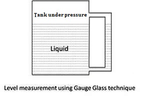
Fig. 24.1 Sight Glass or gauge Glass
24.3 Float Type Level Indicator
It consists of a float which rests on the surface of the liquid. The movement of the float is transmitted to a pointer through suitable mechanism. The pointer indicates the liquid level on a calibrated scale. Various types of floats are used which include hollow metal spheres, cylindrical or disc shaped floats. The float type level indicators are low in cost, reliable and operate over a large temperature range. A float type level indicator for indicating level in a tank is shown in Fig. 24.2a.
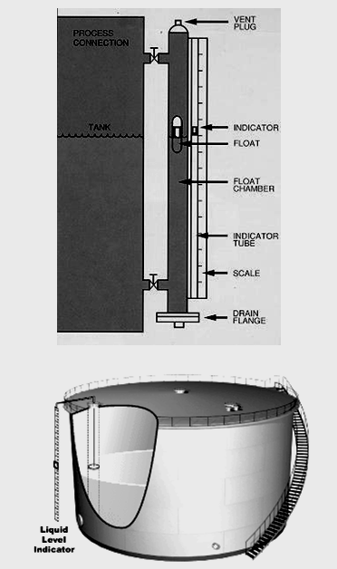
Fig. 24.2 (a) Float type level indicator
The indication of liquid level can be transmitted to a distant place by using hydraulic transmission system also. A float can be used to operate a voltage potential divider (Fig. 24.2 b).
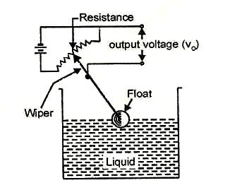
Fig. 24.2(b) Float type level indicator
As the liquid level rises in the tank, the float is raised. Its arm causes the wiper to move over the potential divider whose output terminals are connected to a voltmeter. As a float rises, a greater part of the potential divider is included in the output circuit giving an increased output voltage. Therefore, the output voltage is proportional to the liquid level. The output terminals from the potential divider may also be taken to a remote for display and control.
24.4 Electric Methods
The electric transducers used for level measurements include the resistive, inductive, and capacitive transducers.
24.4.1 Resistive method
This method uses mercury as a conductor and a number of contact rods are placed in such a way that their tips are at various liquid levels in the vessel. As liquid level increases, the rising level of mercury above the datum, shorts successive resistors and increases the value of conductance, thereby indicating the value of liquid height directly. Where there is a need for a fairly continuous record of the level, more and more contact rods can be added, with separate signal outputs for each contact rod. Such a system uses low voltage to eliminate danger to the operators and to prevent arcing at the contact points and the signal thus obtained can be transmitted to have indication at the desired place. These transducers can be used in pressurized containers also. The unit is simple to calibrate. However in order to have a step-less indication of the liquid level, an extremely large number of contact rods are needed. This system also encounters difficulties if there is saturated vapour above the liquid phase. Also any change in the conductivity of the liquid may result in errors.
24.4.2 Inductive method
The inductive level transducers are mainly used for measurement of level of liquids which are conductive. The method employed is based on variable permeability. The arrangement, as shown in Fig. 24.3, uses two coils L1 and L2 wound around a steel tube containing the liquid. The coils are connected in series through a resistance and the circuit is energized by an alternating current source. The inductance of each coil is initially equal. One of the coils acts as the search coil and is set at a predetermined level. The inductance of the search coil changes rapidly as the conducting liquid moves into the plane of the coil. The method works well because the tape material is weakly magnetic and the liquid metal is a conductor which allows eddy currents to flow in it. The relationship between the output voltage and the liquid level is essentially non-linear.
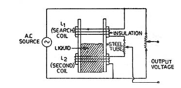
Fig. 24.3 Inductive level indicator
24.4.3 Capacitive methods
Change in capacitance with change in area of plates, distance between plates and the dielectric constant has already been explained in Lesson 16. All these principles are employed in detecting the level of liquids and solids in a container.
i) Variable area method
The variable area capacitive transducer is used for measurement of levels of both solids and liquids. The electrical conducting container containing the materials is used as one connection point of the transducer. The other point is a metal rod completely covered by insulating material inside the container. The insulating material acts as the dielectric medium and the capacitance varies linearly with the height of the material. The relationship is given by:
![]()
Where, e = Permittivity; F/m,
h = Height of material; m,
d1 = Diameter of the metal rod; m, and
d2 = External diameter of the insulator; m.
The container should be earthed to avoid any danger of electric shock to the personnel and to prevent any errors due to external metallic objects.
ii) Capacitive voltage divider method
In case, the conductivity of a liquid is high, its surface can be used as one electrode of the capacitor. The other electrode is a fixed reference plate parallel to the surface of the liquid. A system incorporating these features is shown in Fig. 24.4. This uses an auxiliary electrode P1 placed at a fixed distance above the reference electrode P2. The two electrodes P1 and P2 are electrically insulated from each other. An AC voltage is applied between the liquid and the electrode P1.
![]()
Capacitance C2 is inversely proportional to the distance between the liquid surface and P2. Thus the output voltage decreases with rise of liquid level and therefore the relationship between them is non-linear.
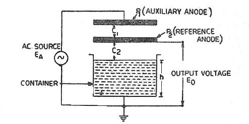
Fig. 24.4 Capacitive voltage divider liquid level gauge
iii) Variable dielectric constant method
If the liquid is non-conducting it can be used as a dielectric in a capacitor. The arrangement for measurement of liquid level for non-conducting liquids is illustrated in the Fig. 24.5. An insulated metal electrode firmly fixed near and parallel to the metal wall of the tank. If the liquid is non-conductive, the electrode and the tank wall form the plates of a parallel plate capacitor with the liquid in between them acting as the dielectric. If the liquid is conductive the rod and the liquid form the plates of the capacitor, and the insulation between them is the dielectric. Where the tank is not of metal, two parallel insulated rods or electrodes, kept at a fixed distance apart are used. The two rods act as two plates of a parallel plate capacitor.
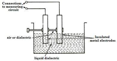
Fig. 24.5 Dielectric liquid level gauge
The capacitance of this capacitor depends, among other factors, upon the height of the dielectric between the plates. The higher the liquid level, the greater is the capacitance. The lesser the height, the smaller is the capacitance. Thus, the capacitance is proportional to the height of the liquid in the tank. The capacitance in the above cases may be measured and this measured capacitance is an indication of liquid levels.
24.5 Measurement of Liquid Level with Gamma Rays
Gamma rays are being increasingly used for detection of liquid levels. A source of gamma rays is placed at the bottom of the tank. At the top of the tank there is a sensor of gamma rays like a Geiger Müller tube. If the tank is empty the intensity of gamma radiation reaching the sensor will be more. But if there is some liquid in it, some of the rays will be absorbed by the liquid and the radiations reaching the tube will be small, and hence its output is small. The higher the level of the liquid, the greater is the absorption and hence lesser will be the output of the Geiger Müller tube. Thus the output of Geiger Müller tube is inversely proportional to the liquid level. The output of the Geiger Müller tube is in the form of pulses which may be counted by a counter. Thus the counter may be directly calibrated in terms of the liquid level.
24.6 Ultrasonic Method
An ultrasonic transmitter receiver can be mounted on the top of tank for measurement of level of either solids or liquids. The beam is projected downwards by the transmitter and is reflected back by the surface of the solid or liquid contained in the tank. The beam is received by the receiver. The time taken by the beam is a measure of the distance travelled by the beam. Therefore, the time ‘t’ between transmitting and receiving a pressure pulse is proportional to the distance ‘h’ between the ultrasonic set and surface of the contents of the tank. As the level in the tank is more, the distance ‘h’ will be less and accordingly the time ‘t’ will be less. The time is then the measure id level of liquid in the tank.
24.7 Level Transmitter for Milk Silos
A pressure gauge is mounted at the bottom of the milk silo. The gauge measures the pressure at the bottom which is proportional to the level. A differential bellow type elastic element and pneumatic amplifier is used for measurement and indication, since the pressure difference with different column heights can be low.