Module 6. Process control
Lesson 32
INSTRUMENTATION AND CONTROLS IN CIP CLEANING AND SANITIZING
32.1 Introduction
Cleanliness is an essential component of process hygiene and a satisfactory hygiene is the statutary requirement of dairy processing industry. Dairy plants need frequent and effective cleaning of equipments. This has led to the equipment designs which are cleaned-in place and the large modern dairy plants employ automated CIP methods. In this system various cleaning, flushing and sanitizing fluids are circulated through the equipment, without dismantling it. Cleaning is achieved by the physical action of high velocity flow jets, agitation and chemical action of cleaning agents. The cleaning action may be enhanced by heating the fluids. Most of the cleaning action is provided by surfactants, acids, alkalis and sanitizers. A CIP system consists of tanks and pipe lines for distribution and return of cleaning agents. It reduces the labour requirement and improves the productive utilization of plant and machinery.
32.2 CIP Cleaning-In-Place
Cleaning-In-Place (CIP) and Sterilization-In-Place (SIP) are systems designed for automatic cleaning and disinfecting of the dairy equipments without major disassembly and assembly work. The CIP system allows cleaning one part of the plant while other areas continue to produce product. Furthermore, a modern CIP system will not only save money in terms of higher plant utilization but also due to significant savings in cleaning solutions, water and labour requirement. The system also ensures the operator safety and minimized product change over time.
CIP (cleaning-in-place) covers a variety of areas but its main purpose is to remove solids and bacteria from tanks, vessels, and pipe work in the dairy processing equipments. The type of cleaning medium or detergents includes caustic, acid, disinfectant, return water and the fresh water. The detergents are usually recycled. The number of CIP circuits depends upon the plant areas to be cleaned and the required availability for the same. The number of tanks in the CIP circuit depends on the required detergent and disinfectant volumes; however the number rarely exceeds 8 tanks per system. The volume of the tanks is as per the effective volume needed for the cleaning. The flow rates of detergents in the system are kept normally up to 150 m³/h.
32.3 CIP System Configuration and Layout
A CIP system consists of piping for distribution and return of cleaning agents, tanks and reservoirs for cleaning solutions, heat exchangers spray heads, flow management devices and programmable control unit. Two main types of CIP systems are available: single-use units, in which all cleaning solutions are used once and discarded and the reuse units which use the cleaning media and rinse liquid more than once. The latter type of system recovers the recirculated alkali which is stored for the next cleaning event. Single use systems are preferred when there is a concern of cross contamination. For acid and alkali recirculation, concentrated solutions are metered into deionized water-filled acid / alkali tanks. The contents of the tank are mixed by recirculation through CIP supply pump. A heat exchanger heats the solution to the desire temperature. Temperature of the return flow is monitored and recorded. The steam supply to the heat exchanger is controlled by the return flow temperature signal during recirculation of the alkaline detergent. Dry running of supply pump is prevented by no-flow sensors. During the final water wash, the conductivity sensor is used to monitor the return flow which is sent to drain when a preset low conductivity value is reached indicating complete removal of acid or alkali from the system. Sensors are provided to monitor the strength of cleaning solutions. Sometimes, the cleaning solutions are dosed in line.
32.4 Automation for CIP
In simple and smaller facilities manual operation of CIP cleaning is followed. CIP cleaning of large or complex processing plant requires automation and micro-processor based controls, with PLCs. The PLCs are programmed with several different cleaning progarmmes, one for each cleaning facility. The programme specifies the cleaning route, sequence of cleaning, the flow rates and the temperatures and strength of cleaning media. The duration of each cleaning programme is fixed. Each control valve in the line is monitored using positive feedback. In the event of a failure the system is designed to safe shut down.
The circuit diagram of automated CIP system is given in the Figure 32.1
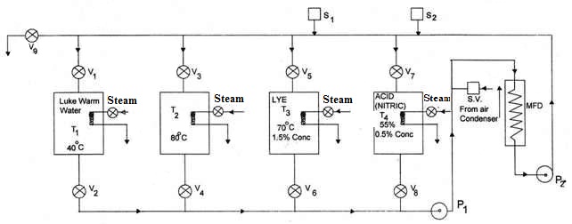
Fig. 32.1 CIP system automation
In the figure the T1, T2, T3, and T4 are the Tanks for luke warm water, hot water, alkali (sodium hydroxide) and nitric acid solutions. The heating is done by steam and the temperature in the tanks is controlled by steam thermostat. The milk flow path is denoted by MFP and all the milk contact surfaces of the equipments such as separator, homogenizers, plate heat exchangers, pasteurizers are connected series. The valves V1 to V9 are the air operated heavy duty valves which are operated by pilot valves. The valve V9 is the drain valve. P1 and P2 are the forward and the return flow pumps respectively. SV represents the solenoid valve for compressed air flow. S1 and S2 are the Solution Analyzers to control the concentration of Lye and Acid solutions respectively. The Wheatstone Bridge type circuit is used where the conductivity (electrical conductivity) of the solutions are compared to operate and control solution valves for injecting on to CIP lines. The operation of the CIP system is illustrated in Figure 32.2.
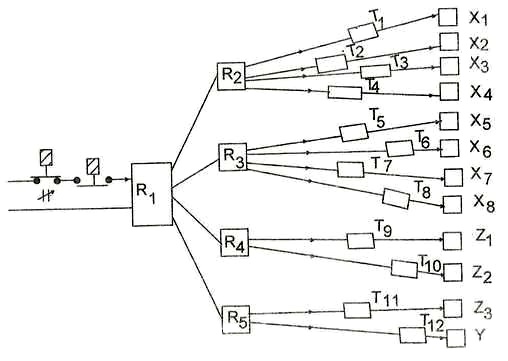
To start the system the start button ST is switched on. This in turn switches on the Electromagnetic Switching Relays R1 to R5. Now the power is ready for all the valves. The various valves in the CIP system include; X1 and X2 which are the air operated pilot valve for the Rinse Water, X3 and X4 for Lye Solution, X5 and X6 for Hot Water flow, X7 and X8 for Acid solution, Z1 is the compressed air solenoid valve, Z2 CIP drain valve and Z3, Y are the solution analyzers valves. The power supply is controlled by electronic timers T1 to T12, which switches on / off at different times set for various valves for flow of cleaning solutions.
32.5 Automatic Chlorinator
A simple automatic chlorinator using venturi flow meter is shown in figure 32.3. It consists of a balloon of a flexible material which contains the chlorine solution. The flexible balloon is placed in a fixed metallic or PVC drum. A venture tube is placed in the water supply line. Pressures across the venturi tube are sensed and this pressure differential drives the flow if chlorine solution (i) to the water line. The quantity of chlorine solution injected is proportional to the pressure differential (P1-P2) which in turn is proportional to the flow of water. Hence chlorine is injected at the constant rate to the water line. The system is designed for 50 ppm of free chlorine.
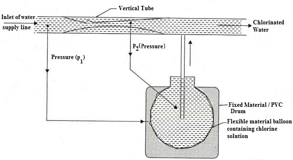
Fig. 32.3 Automatic chlorinator