Module 5. Air cycles
Lesson 10
OTTO CYCLE AND DIESEL CYCLE
10.1 Introduction
In case of reversible cycles, the thermal efficiency depends only on the operating temperatures and not on the type of ‘working substance’. This thermal efficiency is maximum possible efficiency and same for any of reversible cycle operating between same temperature limits irrespective of the working substance used. But in actual practice, the reversible heat transfer i.e. heat transfer at constant temperature is not possible. In real conditions, some temperature difference between heat reservoir and working substance is needed and also during heat exchange process, the temperature of working substance changes. Thus the real heat exchange process is always irreversible and the cycle containing this process is also irreversible. The change in temperature during heat absorption or rejection process or the capacity of heat exchange depends on the properties of working substance. Thus the thermal efficiency of irreversible cycles depends also on the nature of working substance. Now to compare the efficiency of different types of irreversible cycles, some common working medium, which is somewhat near to ideal gas should be used. For this purpose, air which is assumed to behave as a perfect gas is taken and the real irreversible cycles having air as working medium are called air cycles. The working of an air cycle is further based on certain assumptions and the thermal efficiency of air cycle based on these assumptions is called ‘Air-standard efficiency’ sometimes also called ideal efficiency.
10.2 Air Cycles
10.2.1 Air cycle assumptions
The analysis and working of air cycles is based upon the following assumptions:
1) Air is a perfect gas which obeys the gas laws and has constant specific heats.
2) The physical constant of air used in Air cycles are taken as: Molecular weight=29, Specific heat at constant pressure, Cp = 1.004 kJ/kg K; specific heat at constant volume, Cv = 0.717 kJ/kg K; Characteristic gas constant, R = 287 J/kg K
3) The compression and expansion processes taking place in an Air-cycle are reversible adiabatic or isentropic i.e. there is no internal friction and other losses.
4) No chemical reaction or change takes place in air while undergoing the cycle and heat is supplied to or rejected by the air by bringing a hot body or cold body in indirect contact with air working in an irreversible or real heat engine.
5) The air cycle is considered to occur in a closed system i.e., the same air quantity undergoes the cycle again and again and there is no replacement of it during working of heat engine based on air cycle.
10.2.2 Air standard efficiency
The thermal efficiency of an air cycle, which is considered to work on the basis of above mentioned assumptions, is known as air standard efficiency. This air cycle is considered as a standard for the working of a real heat engine. So it is also known as ideal efficiency of a real heat engine. It can be calculated by making theoretical analysis of a given air cycle and works as a standard of comparison for the real or actual thermal efficiency.
10.2.3 Actual thermal efficiency
This is simply the ratio of actual work output to the actual heat absorption rate of a heat engine. It can be calculated by actually measuring the power output and heat absorption rate of a heat engine. It may vary in the varying conditions:
![]()
10.2.4 Relative efficiency
It is the ratio of actual thermal efficiency to the air standard efficiency of a heat engine under the same working conditions.
10.3 Otto Cycle
The ‘Otto’ cycle is named after its inventor “Nikolaus A Otto”. This cycle works as a standard for Petrol or gas engine, because it suits to their combustion properties. The cycle is shown on P-V and T-S diagrams in fig 10.1(a) and 10.1(b). The cycle is also visualized to occur in a reciprocating engine shown below the P-V diagram.
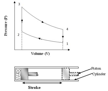
Fig
10.1 (a) Otto Cycle on P-V Chart
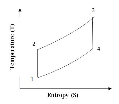
Fig 10.1 (b) Otto Cycle on T-S Chart
Process-wise description of the complete cycle is as given below:
Process 1-2(Adiabatic compression)
At condition ‘1’, the piston is at lower end position and air filled in the cylinder behind the piston is having total volume of cylinder, V1 at pressure P1. Then the piston is moved from lower end position to upper end position ‘2’ by external force and so total volume of air V1 is adiabatically compressed to clearance volume of cylinder ‘V2’. The walls of cylinder are consider insulated such that there is no heat exchange between air and cylinder walls and also there is no internal friction or internal loss of energy. Due to this reversible adiabatic compression, the pressure and temperature both rises to a new value of P2 and T2. The compression ratio is not too high and limited between 7 to 9 in ‘Otto’ cycle engine.
Process 2-3 (Constant volume heat addition)
In this process some heat source comes in contact with the cylinder head and heat is transferred to compressed air while remaining at volume V2. It means the piston remains at rest for the time heat is transferred to compressed air. Due to this constant volume heat addition, the pressure and temperature of air shoots up further and it reaches to the condition ‘3’ of very high pressure, high temperature but at same volume. The constant volume heat addition can be calculated as: Q = m.Cv.∆T.
Where, m = mass of air in the cylinder
Cv = Specific heat of air at constant volume
∆T = Rise in temperature from condition 2, to ‘3’.
Process 3-4: Adiabatic expansion
This process is reverse of the adiabatic compression process 1-2. Initially at condition ‘3’ the air in the clearance volume of cylinder is at very high pressure and temperature i.e., at higher energy level and so it expands adiabatically to a lower pressure and temperature and doing positive work on the piston. In this process actually the part of energy of air converts to mechanical work and air comes to a low energy level at condition ‘4’. The piston is pushed by expanding air to lower end position and air returns to its original volume ‘V1’.
i.e., V1 = V4.
Process 4-1 (Constant volume heat rejection)
In the previous process 3-4, air has expanded to the total volume of cylinder, but its pressure and temperature are still higher than initial values at the start of cycle shown by condition ‘1’. So in the process 4-1, a heat sink comes in contact with cylinder head and air rejects its heat remaining at constant volume and its pressure and temperature drops to the same initial values P1 and T1. In this way the Otto cycle completes.
During one complete ‘Otto’ cycle, the piston undergoes two strokes. In one stroke external force is applied on the piston and air is compressed and in other stroke air expands and does positive work on the piston. The compression work is shown by the area under compression process 1-2 on P-V diagram and expansion work is shown by the area under expansion process 3-4 on P-V diagram. Net work output per cycle is expansion work minus compression work which is shown by the area covered by cycle 1-2-3-4 on P-V diagram. The thermal efficiency of ‘Otto’ cycle can be calculated by the following mathematical analysis:
Let us consider there is one kg of air trapped behind piston in the cylinder.
So heat absorbed by 1 kg of air at constant volume = Cv (T3 - T2)
Heat rejected by this air at constant volume = Cv (T4 – T1)
We know that there is no heat exchange during compression or expansion processes. So by energy balance of one cycle.
Work Output = Heat absorbed – Heat rejected = Cv (T3 - T2) - Cv (T4 – T1)
Therefore, ideal efficiency or air standard efficiency of ‘Otto’ cycle is given as
η = Work output/ Heat absorbed
![]() ………
(i)
………
(i)
We know that for reversible adiabatic compression process 1-2.
![]()
![]() ………
(ii)
………
(ii)
Similarly for reversible adiabatic expansion process 3-4,
![]()
![]() ………
(iii)
………
(iii)
From equations (i), (ii), (iii) we find that
![]() ……… (Eq.
10.1)
……… (Eq.
10.1)
This is
the air standard efficiency of ‘Otto’ cycle and from the expression it is clear
that efficiency, η increases with increase in compression ratio ‘r’. But
in actual ‘Otto’ cycle engine the compression ratio cannot be increased beyond
a value 9 or so due to other practical difficulties associated with the
combustion of petrol or Gasoline.
10.4 Diesel Cycle
This cycle was devised by Dr. Rudolph Diesel in 1893. This cycle works as a standard cycle for a Diesel engine as the heat absorption process here resembles the combustion and heat release properties of Diesel fuel. The cycle is shown on P-V and T-S diagram in fig. 10.2 (a) & 10.2 (b). It is different from ‘OTTO’ cycle only in the heat absorption process which is a constant pressure process here. During this process, piston moves some distance and takes some finite time which resembles the slow rate of heat realease in the combustion of Diesel.
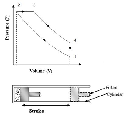
Fig
10.2 (a) Diesel Cycle on P-V Chart
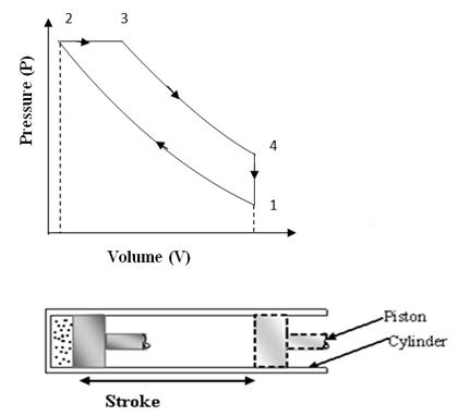
Fig 10.2 (b) Diesel Cycle on T-S Chart
Process- wise description of the complete cycle is as given below:
Process 1-2: (Adiabatic compression)
At condition 1, the piston is at lower end position and air filled in the cylinder behind the piston is having total volume of cylinder, V1 at pressure P1. Then the piston is moved from lower end position to upper end position ‘2’ by external force and so total volume of air V1 is adiabatically compressed to clearance volume of cylinder ‘V2’. The walls of cylinder are considered insulated such that there is no heat exchange between air and cylinder walls and also there is no internal friction or internal loss of energy. Due to compression, the pressure and temperature both rises to new value P2 and T2. The compression ratio r=V1/V2 is on higher side in this cycle. It is generally in the range of 15 to 22.
Process 2-3: Constant pressure heat addition
Here in this process, some heat source comes in contact with the cylinder head and heat is transferred to the compressed air at constant pressure. That means in this process heat is added in comparatively a slow process and air keeps on expanding while absorbing heat. This kind of heat addition resembles the heat gain by engine during combustion of Diesel. At the end of process, air has partially expanded thus doing some work also, simultaneously with absorption of heat. The ratio of volume V3 of air, where heat supply is cut, to volume V2 (clearance volume) is called cut off ratio, ρ. The constant pressure heat addition can be calculated as Q = m Cp ∆T.
Where m = mass of air in the cylinder
Cp = Specific heat of air at constant pressure
∆T = Rise in temperature from condition ‘2’ to ‘3’.
Process 3-4: Adiabatic expansion
In this process, air at condition of high pressure and temperature expands adiabatically on its own and does mechanical work by pushing the piston further to initial position or lower end positions. During this process, there is no exchange of heat energy between air and its surroundings and only internal energy of air at condition 3 is converted to mechanical work. The final volume V4 of air at the end of process is same as initial volume V1, i.e., V1=V4.
Process 4-1: (Constant volume heat rejection)
In the previous expansion process 3-4, air has expanded to the total volume of cylinder, but its pressure and temperature are still higher than initial values at the start of cycle shown by condition ‘1’. So in the process 4-1, a heat sink comes in contact with cylinder head and air rejects its heat, remaining at constant volume. Its pressure and temperature drops to the same initial values P1 and T1. In this way the cycle completes.
During one complete Diesel cycle, the piston undergoes two strokes. In one stroke, external force is applied on the piston and air is compressed and in other stroke air expands and does positive work on the piston. The compression work is shown by the area under compression process 1-2 on P-V diagram and expansion work is shown by the area under expansion process 3-4 on P-V diagram. Net work output per cycle is expansion work minus compression work which is shown by the area covered by cycle 1-2-3-4 on P-V diagram.
The thermal efficiency of ‘DIESEL’ cycle can be calculated by the following mathematical analysis:
Let us consider there is one kg of air trapped behind piston in the cylinder.
So heat absorbed by 1 kg of air at constant pressure = CP (T3 - T2)
Heat rejected by 1kg of this air at constant volume = Cv (T4 – T1)
We know that there is no heat exchange during compression or expansion processes. So, by making balance of ‘energy exchange’ in one cycle.
Work Output = Heat absorbed – Heat rejected = CP (T3 - T2) - Cv (T4 – T1)
Therefore, ideal efficiency or air standard efficiency of ‘DIESEL’ cycle can be calculated as:
η
= Work output/ Heat absorbed
![]() ………
(i)
………
(i)
where CP/ Cv = γ (Ratio of specific heats at constant pressure and constant volume)
We know that for reversible adiabatic compression process 1-2.
![]()
So,
T2 = T1rγ-1 ……… (ii)
For constant pressure process 2-3,
![]()
By putting (ii)
here,
T3 = ρT1rγ-1 ……… (iii)
From reversible adiabatic expansion process 3-4
![]()
∵V4 = V1 = Total volume and V2 =clearance volume
![]()
T4 = ργT1 ………..(iv)
Now putting the values of equation (ii), (iii) & (iv) in (i):-
![]()
![]() ……… (Eq.
10.2)
……… (Eq.
10.2)
This is air standard efficiency of ‘DIESEL’ cycle and from the equation 10.2 it is clear that it increases with increase in compression ratio ‘r’.
Note:
Form the expressions of efficiency of ‘OTTO’ & ‘DIESEL’ cycles it is clear
that as the value of ρ & r each is always
more than 1, so for same compression ratio, the efficiency of an ‘OTTO’ cycle
is more than that of ‘DIESEL’ cycle. But in actual practice, due to practical
reasons, the compression ratio of an ‘OTTO’ cycle is limited between 7 to 9,
while for a Diesel cycle, it is not limited and varies in the higher range of
16 to 22. Therefore practically, a Diesel engine is more efficient than a
Petrol Engine, due to higher value of compression ratio.