Module 6. I. C. engine
Lesson 15
FUEL SUPPLY SYSTEMS
15.1 Fuel Supply System of S.I Engine
In a S.I engine, a measured quantity of petrol or gas is already mixed with air in a calculated proportion before being sucked by engine. Then this combustible charge having right quantity of fuel-air is ignited at the appropriate time at the end of compression stroke in the engine with the help of a spark plug. The operation of spark plug is timed along with the moment of crank shaft with the help of ignition system. Low voltage of battery is given to primary winding of ignition coil through an ignition switch and contact breaker. The secondary winding is connected to spark plugs through distributor (in case of multi-cylinder engines). A cam on cam shaft breaks the contact and causes the electric primary circuit to open and close. When the circuit is broken or the current flow is stopped in the primary winding, the magnetic field collapses inducing a high voltage in the secondary winding due to which a spark occurs instantaneously in the spark plug. This spark initiates the combustion of compressed air-fuel mixture in the engine cylinder.
Depending on the method of mixing petrol or gas in the air in right proportion as per the requirement of engine, the fuel supply system of S.I engine is conventionally is of two types as discussed below
15.1.1 Carburetion
In the carburetion method, fuel stored in the fuel tank is supplied to carburetor by means of a simple diaphragm pump through a fuel filter. The job of pump is only to supply fuel from fuel tank to float chamber of carburetor. Sometimes when the fuel tank is above the carburetor like in 2-wheeler engine, fuel will come by gravity and fuel pump is not needed.
The design & working of a simple carburetor fitted in the suction line or Inlet manifold of engine is very simple. As shown in fig 15.1 there is a venturi in the flow passage of air being sucked by engine? A jet is situated in the venturi and connected to the float chamber of carburetor, where fuel is stored at atmospheric pressure. The float keeps the fuel at a constant level in the float chamber. While passing through the venturi, pressure of air reduces and a pressure difference is created across the fuel jet connecting float chamber with venturi. Due to this pressure difference fuel is continuously supplied to air flowing through venturi. As jet is of very small inner diameter, fuel i.e. petrol is sprayed in the flowing air and due to its high volatility, it vapourizes and forms a combustible mixture of fuel vapour plus air. The fuel air ratio is automatically controlled by the speed of air through the venturi which eventually depends on speed/rpm of engine. The size of venturi and jet are designed on the basis of desired fuel air ratio. In an actual carburetor, some additional systems are there to satisfy the demands of engine under varying conditions like cold starting, engine idling, requirement of additional power at high speed & load etc. (Fig. 15.1)
15.1.2 Electronic fuel injection (MPFI system)
In this system an electrically driven fuel pump draws fuel from fuel tank and supplies it to a common header or tube. A pressure regulator fitted at the end maintains a constant pressure of fuel approx. 3 bars in the header. The header is connected to different branches of inlet manifold through fuel injectors. For each cylinder of engine there is separate fuel injector which injects fuel in the corresponding air passage of that cylinder. Due to this the system is called multi-point fuel injection (MPFI) system. The fuel injectors are precision built solenoid valves having single or multiple orifices. Due to constant pressure of fuel maintained in the common header, the quantity of fuel injected depends only on the time period for which the solenoid valve type fuel injectors are kept in open position.
An on-board ECU (Electronic control unit) i.e. microprocessor controls the quantity of fuel injected to each cylinder individually and also the ignition timing of each cylinder. The data input to the ECU comes from a number of sensors located all over the engine. These sensors collect the following data continuously.
1. Ambient temperature
2. Inlet manifold vacuum or Air Velocity
3. Exhaust gases temperature
4. Exhaust O2 content
5. Throttle position
6. Engine r.p.m.
7. Crankshaft & position
8. Engine coolant temperature
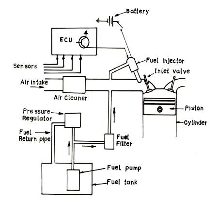
Fig. 15.2 Electronic fuel injection system
Based on programmed interpretation
or processing of this data, ECU calculates the amount of fuel needed to
maintain stoichiometry i.e. air/fuel ratio of 14.7:1 and converts it into
required pulse width i.e. time period for which it keeps the solenoid injector
energized. ECU also gives command to spark ignition system. In this way ECU
ensures overall satisfactory performance of the engine from start to shut down
including emission control by sending right quantity and quality of fuel air
mixture to each cylinder of engine at right time based on requirement of engine
and also ignites it at right time.
15.2 Fuel Supply System of C.I Engine
The primary requirement of a C.I engine is to inject the right quantity of fuel at a very high pressure either directly over the piston in the cylinder of engine or indirectly in a combustion chamber in the cylinder head which is connected to cylinder of engine. In any method the fuel injection system has to control injection timing, injection period and injection pressure. Now in most of the diesel engines direct injection is used with improved injection technology. The diesel injection systems used nowadays are of two types:
(1) Mechanical Injection System
(2) Electronic Injection System
15.2.1 Mechanical injection system
This system was universally being used in Diesel Engines until the introduction of new fuel injection technology like CRDI etc. But still due to the reason of more initial cost involved in adopting newer technology, it is being used in Diesel Engines of different sizes. In this type, there are two basic components as one pressurizing unit (High Pressure Pump) and other atomizing unit (High pressure nozzle or injector). Depending on the design, manner of operation and control of these two basic components, mechanical fuel injection system are of three types.
(a) Individual pump and injector system
In this system there is a separate pump and separate injector for each cylinder of engine. The pump creates high pressure of fuel and also meters and times the injection of fuel through injector. It is a plunger type pump driven by engine power itself.
(b) Common rail system
Here a high pressure pump keeps constant high pressure of fuel in an accumulator with the help of a pressure regulating valve. This accumulator is connected to common rail which is extended to different distributing elements of each cylinder. A separate metering & timing element controls the supply of metered & timed pressurized fuel to each injector of cylinder. This system is self governing and more smooth operation is there.
(c) Distributor system
Like the first system, here also the pump pressurizes, times and meters the fuel. But which quantum of fuel is to be supplied to which injector, is decided by a rotating distributor. This system is cheaper than first system in case of a multi-cylinder engine.
The diagram of a plunger type pump and fuel injector is shown in Fig. 15.3.
15.2.2 Electronic injection system (with CRDI technology)
In this system of diesel injection, a common rail diesel injection (CRDI) technology is used. It is more or less same as Common Rail System of Mechanical Injection but the difference comes in the control over metering & timing of injectors which is done by an on-board computer system or electronic control unit. Thus it resembles with the operation of MPFI system of S.I engine. The basic system is same; there is a high pressure fuel pump which maintains high pressure in a common rail (steel tube) through high pressure regulator. But here the pressure maintained is very high of the order of 2000 bar as compared to 3-5 bars in MPFI system. The fuel injectors are very special either solenoid type or piezzo electric type which control the fuel injection from common rail to each cylinder very precisely.
The opening time, pulse width etc of fuel injectors can be electrically controlled by the E.C.U. Here is the main advantage of system that the fuel can be injected in more than one pulse in a very controlled manner unlike only one pulse or one injection per cycle in the mechanical system. Here a pilot injection is done before the main injection for fast burning and less ignition delay of the fuel. It reduces the noise level very much and also ensures complete burning of fuel, high efficiency, low emission and good cold start. This new technology has considerably removed the demerits of diesel engines like high noise level, high pollution, difficulty in starting etc and improved fuel efficiency a lot. A schematic diagram of CRDI system is given here in fig.15.4

Fig. 15.4 Common rail diesel injection system
15.3 Knocking in S.I. Engine
It is a knocking sound coming from engine due to momentarily steep rise in pressure and temperature during combustion. One theory behind this is when flame (burning and expanding fuel air mixture) propagates from spark plug to the far end of combustion chamber the un-burnt mixture at end is compressed and may self ignite before reaching the flame. Due to that the pressure waves strike each other and pressure increases sharply and due to vibration a knocking sound is produced.
High compression-ratio and the high bulk-temperature increase the tendency of knocking. But mainly knocking tendency depends on the quality of fuel indicated by OCTANE NUMBER. A higher Octane number fuel will have less knocking tendency. Actually the self burning tendency of petrol-air mixture at a lower temperature limits the compression ratio in S.I. Engine.
Normally, Petrol available in India has Octane No. 80 to 90.
15.4 Detonation in CI Engine
It depends on ignition delay. If ignition delay of type of fuel (diesel) used is more than ignition is delayed after injection of fuel. By that time quantity of fuel injected is more and hence more fuel burns simultaneously at a time, releasing more energy in short time. This results in sharp increase in pressure giving a detonating sound. To avoid detonation ignition delay should be less unlike S.I. Engine where it should be more.
The detonating quality of Diesel fuel is specified by its Cetane Number. Higher the Cetane number, lesser will be the propensity of Diesel knocking or detonation.