Module 8. Fuels
Lesson 21
DETERMINATION OF CALORIFIC VALUE, OIL BURNERS
21.1 Calorific Value
The calorific value or heating value of the fuel is defined as the energy liberated by complete oxidation of unit mass or volume of a fuel. It is expressed in kJ/kg for solid and liquid fuels and kJ/m3 for gases.
21.1.1 Higher and lower calorific value
Basically all fuels contain carbon and hydrogen. During combustion process, carbon burns to carbon dioxide and hydrogen reacts with oxygen and forms water vapor. The magnitude of calorific value depends on the phase of water vapor in the products of combustion.
The higher heating value, HHV or gross calorific value is obtained when the water formed by combustion is completely condensed. The lower calorific value (LHV) or net calorific value is the amount of heat released by complete combustion of unit quantity of fuel, when vapor carries its heat of vaporization.
Thus,
(HHV)p = (LHV)p + m.hfg
(HHV)p = (LHV)v + m (ug – uf)
Where
m = mass of water vapor formed by combustion
hfg = Enthalpy of vaporization of water, kJ/kg
ug = specific internal energy of vapor kJ/kg
uf = specific internal energy of liquid
21.2 Determination of calorific value of a fuel
The calorific value can be determined either from chemical analysis by Dulong’s formula or in the laboratory by any experimental method.
21.2.1 Calorific value of solid & liquid fuels
Dulong suggested a formula for the calculation of calorific value of the solid & liquidfuels from their chemical composition which is given below:
H.C.V = 338800 × C + 14400 × [H2 - O2 /8] + 9270 × S
Where C, H, O and S are carbon, hydrogen, oxygen and sulphur in percentage constituents respectively in 1 kg of fuel.
(a) Laboratory method (Bomb Calorimeter)
The calorific value of powdered and liquid fuel is determined at constant volume in Bomb calorimeter. It resembles the shape of bomb, and thus known as bomb calorimeter.
The calorimeter is made of austenitic steel which provides considerable resistance to corrosion and enables it to withstand high pressure. The fuel sample is placed in crucible inside the bomb, which is filled with oxygen under a pressure above 25 atm. The calorimeter is filled with water jacket with a jacket of water and air. A stirrer for keeping the temperature of water uniform and a thermometer to measure the temperature up to accuracy of 0.001oC is fitted through the lid of calorimeter.
Procedure
To start with 1 gm of fuel sample as a briquette is placed into the crucible and a fuse wire is connected with electrode as shown in Fig. 21.1. To absorb the combustion products of sulphur and nitrogen, 2 ml of water is poured in the bomb. Bomb is then supplied with pure oxygen through the valve to an amount of 25 atm. The bomb is then placed in weighed quantity of water, in the calorimeter. The stirring is started after making necessary electrical connections, and when calorimeter indicates a steady state temperature, fuel is fired and temperature readings are taken; the pressure is slowly released through, the exhaust value and the contents of bomb are carefully weighed for further analysis. The heat released by combustion of fuel is absorbed by water surrounding the bomb and calorimeter. From the above data, the calorific value can be found in the following way:
Heat released by fuel sample = wf.C
Heat received by water and calorimeter = (Ww+We) × c × [ (t2-t1) + tc]
By energy balance
wf.C = (Ww+We) × c × [ (t2-t1) + tc]
![]()
Where
wf = weight of fuel sample, kg
w = weight of water, kg
c= specific heat of water
C = calorific value (higher) of fuel, kJ/kg
we = water equivalent of calorimeter (kg)
t1 = initial temperature of water and calorimeter
t2 = radiation cautions
Example
Ultimate analysis of a sample of coal is given as
C = 84.4% H = 4%
O = 5.6% Ash = 6%
Find: Higher & lower calorific value of fuel for complete combustion
Analysis
![]()
![]()
![]()
![]()
![]()
![]()
21.2.2 Calorific value of gaseous fuel
The calorific value of a gaseous fuel is determined by Junker’s or Bry’s gas calorimeter. The metered gaseous fuel is continuously supplied to calorimeter at constant pressure, where it is burnt in presence of air as shown in fig 21.2. In its simplest construction, it consists of a combustion chamber in which the gas is burnt. A water jacket through which a set of tubes called flue gas pass surrounds this chamber. Thermometers are incorporated at different places to measure the temperatures.
Procedure: A metered quantity of gas whose calorific value is to be determined is supplied to the gas burner via a gas meter which records its volume and a gas pressure regulator which measures the pressure of the gas by means of a manometer. When the gas burns, the hot products of combustion travel upwards in the chamber and then downwards through the flues and finally escape to the atmosphere through the outlet. The temperature of the escaping gas is recorded by the thermometer fitted at the exit and this temperature should be as close to room temperature as possible so that entire heat of combustion is absorbed by water. The cold water enters the calorimeter near the bottom and leaves near the top. Water which is formed by condensation of steam is collected in a pot.
The quantity of gas used during the experiment is accurately measured by the meter and temperatures of ingoing and outgoing water are indicated by the thermometers. From the above data the calorific value of the gas can be calculated.
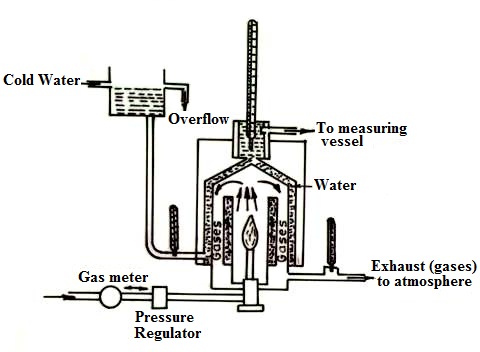
Fig. 21.2 Junker’s gas calorimeter
Example
The following results were obtained during the trial on gas calorimeter. Gas supplied = 0.8 m3 at 32°C. Pressure of gas = 40 mm of water, Barometric reading 750 mm; Temperature of water at inlet and outlet as 30°C and 38oC respectively. Mass of cooling water circulated = 24 Kg; specific heat of water = 4.2 kJ/ kg K; steam condensed = 0.055 Kg. Determine the higher and lower calorific value of fuel at 25oC. Assume standard barometric pressure = 760 mm of Hg. Take hfg= 2442.5 kJ/ kg K, at 25oC.
Solution
Vgas = 0.8 m3
Tgas= 32oC = 305 K
Pgas = 40 mm water above 350 mm Hg
mw = 24 kg ms = .055 kg
cw = 4.2 kJ/ kg K hfg = 2442.5 kJ/kg K
T = 25oC
p = 750 mm Hg
Pgas = Pgage + patm
= 40 mm H2O + 750 mm Hg
= ![]()
= ![]()
= ![]()
Standard barometric pressure
p = 760 mm Hg
= ![]()
= ![]()
Volume of gas at standard reference state
![]()
![]()
![]()
The higher caloric value is
21.3 Oil Burners
For liquid fuels to burn satisfactorily, they must first be brought into the vapour state and burners may be classified by the method which is employed to do this. Different method of vaporization may be adopted, but all burners operating on direct vaporization are referred to as vaporizing burners. Light fuels such as kerosene and gas oil can be vaporized by the direct application of heat. If this technique is applied to the heavier oils, the temperature required to evaporate the fuel also produces severe ‘cracking’ and solid carbon particles are produced. The method adopted to overcome this difficulty is to vaporize in a two-stage process, first by atomizing the oil, or more correctly, by breaking down the oil into a fine spray or mist of oil particles and then by vaporizing these fine oil particles during the actual combustion process.
21.3.1 Vaporization Burners
(a) Wick Burners- As the name implies, a wick is used, and if smoke-free operation is to be maintained, attention should be given to ensure that the burner is clean and correctly adjusted. The flame should be sufficiently close to the wick to evaporate the fuel at the desired rate and yet be sufficiently far away from the wick to eliminate ‘cracking’ of the fuel.
(b) Carburetor Pot Burner—Pot burners dispense entirely with a wick and may operate either on natural or forced draught, depending upon the rate of combustion required. In the natural draught units, the rate of evaporation is controlled by the heat received from the flame only and the oil vapour produced mixes with the air induced by the chimney effect. The draught available at the combustion chamber is usually adjusted to between 0.5 mm and 2.5 mm of water gauge as compared with 0.5 to 5 mm of water gauge with forced draught. With the latter, however, part of the air is directed to the surface of the fuel and thus increased the rate of evaporation. The additional air is also effective in burning off carbon which is deposited on the pot. A typical carburetor or pot-type burner which operates on natural draught is shown in figure 21.3.
21.3.2 Atomizing Burners
The majority of industrial burners and some domestic burners too, employ the atomizing principle of preparing the fuel for combustion. Most of these burners are capable of giving a satisfactory performance, although the method of producing the atomized spray of fuel varies widely. These burners can be classified into three main groups according to the method of atomization used.
(i) Mechanical (Pressure jet).
(ii) Two fluid—air or steam
(iii) Mechanical –assisted by air or steam
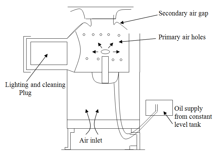
Fig. 21.3 Carburetor or pot-type burner
In order to get good atomization of all but the lightest grades of oil, it is first essential to lower its viscosity by raising its temperature. The recommended viscosity for good atomization is 0.25 S. The most suitable temperature to which the oil should be preheated therefore depends mainly on the type of oil and to a lesser extent on the type and size of the burner. The temperature listed in Table 21.1 may be taken as a general guide for the range of oil quoted.
Table 21.1 Atomizing temperature for petroleum based oils
|
B.S. fuel class |
Kinematic viscosity of oil at 50°C (C Stokes) (max.) |
Atomizing temperature (°C) |
|
E F G H |
36 125 370 690 |
60 88 110 121 |
(a) Mechanical Pressure Jet: The pressure required to obtain good atomization is between 3.5 and 35 bar.
Atomization of the fuel is effected by converting the pressure energy of the oil into kinetic energy with the result that the oil is emitted as a fine mist. In general, the oil passes through a swirl element and then through an orifice from which it issues in the form of a hollow cone. A typical commercial pressure jet atomizer mainly used for steam generation application is shown in figure 21.4. The output of a pressure jet unit of this type varies approximately as the square root of the pressure and over the range of pressures normally used, the turn down or the range of output is limited to about 2-1.
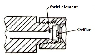
Fig. 21.4 Typical Pressure Jet Atomizer
In spill-type pressure jet atomizers, the range is increased appreciably by recirculation of part of the oil to maintain a high degree of swirl at all outputs. Development of this type of burner was instigated by the urgent demand for good turn-down characteristics in the burners used for jet propelled aircraft, where the gas turbine required a turn-down in the region of 10-1. Today many industrial oil burner systems for general application are operated with spill-type atomizers.
Figure 21.5 (a) and (b) show two designs of spill type atomizer. In the one shown in Figure 21.5(a), the oil is fed under pressure through an annular ring into the swirl chamber which has two exits. One is discharge orifice and the other is the line leading back to the pump for recirculation of the oil. It will be observed that the re-circulated oil is led off axially from the centre of the unit. The amount of fuel, which is re-circulated, is under complete control, and by this means the velocity of swirl can be maintained reasonably constant down to low consumptions of fuel and therefore good atomization is attained over the full working range.
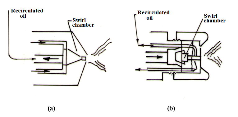
Fig. 21.5 Spill type pressure atomizer
The spill-type atomizer shown in Figure 21.5 (b) has an axial fuel inlet from which independent tangential nozzles impart a rotary motion to the fuel in the swirl chamber. The re-circulated oil is tapped off at the periphery of the discharge nozzle and is returned for recirculation through the annular passage shown.
In some types of spill atomizer the re-circulated oil is bled off at the periphery of the swirl chamber, which has certain advantages, but for low flow conditions, it would appear that maximum atomization will occur when the bleed-off is as near to the final orifice as is practicable, that is, the maximum swirl is obtained at the discharge orifice.
Control system for normal industrial applications to furnaces and boilers are relatively simple, but the automatic controls for the application to gas turbines for aircraft are extremely complicated pieces of mechanism.
(b) Two-fluid Atomizers The atomization of the fuel in this type of burner is carried out by using the kinetic energy of a stream of a second fluid at a relatively high velocity. The atomizing fluid is normally steam or air. Air jet atomizers are manufactured in three arbitrary groups depending upon the air pressure employed.
Low pressure Up to 760 mm w.g. (fan)
Medium pressure 13.8 to 69 kPa (rotary compressor)
High
pressure
69 to 1035 kPa (piston compressor)