Module 10. Steam generators
Lesson 25
BOILER MOUNTINGS AND ACCESSORIES
25.1 Boiler Mountings
These are the fittings, which are necessarily mounted on the boiler itself and mandatorily required for the safe and proper operation of boiler. Various boiler mountings are being discussed here one by one.
25.1.1 Water level indicator
25.1.1.1 Function
Water level indicator is fitted outside the boiler shell to indicate the water level in the boiler through a glass tube. In any type of boiler, water should remain at the designed level. If the water falls below the level due to change of phase into steam and simultaneously fresh water does not fill in by some reason, the hot surface may expose to steam only and overheat. This is because the heat transfers co-efficient of steam is very less as compared to water. Due to overheat, damage of tube surface may occur. To avoid this situation, level of water in the boiler needs to be constantly monitored & maintained by boiler operator by keeping watch on water level indicator.
25.1.1.2 Construction
As shown in the Fig 25.1, two horizontal tubes made of gun metal extend from the boiler shell in such a way that top one is connected to steam space and bottom one is connected to water space of the boiler. These are connected at the other end by a vertical glass tube contained in a hollow casting in such a way that water and steam come out in the glass tube and their interface is visible through it. Each gun metal tube is also provided with a cock to control the flow of water/steam to the glass tube. One drain cock is fitted at the bottom for cleaning purpose. The horizontal metal tubes also contain one metal ball each which normally rests on a hemispherical groove in the tubes. In case the water/steam rush with high speed as may be if glass tube breaks by accident, this ball lifts up from its normal position and block a hole which connects the metal tube with glass tube and stops the flow.
25.1.1.3 Working
Working of water level indicator or water gauge is very simple. When the cocks are opened, boiling water and steam from the boiler shell flow into the hard glass tube and maintain the same level as in the boiler which is visible to operator. When the water level falls down beyond a safe limit, operator may switch on the feed pump to fill more water in the boiler shell. In the water and steam passages in the gun metal tubes, a metal ball rest in the cavity made in the passage. In case of breakage of glass tubes by accident, water and steam contained at high pressure in the boiler rush with high speed towards broken glass tube due to large pressure difference between inside and outside of boiler. Due to this, the ball resting in the cavity made in the passage lifts and rushes towards the end of gun metal tube and blocks the passage of steam or water flow. Then immediately the cock can be closed and glass tube can be replaced safely.
25.1.2 Pressure Gauge
25.1.2.1 Function
A pressure gauge is used to indicate the pressure of steam in the boiler. It is generally mounted on the front top of the boiler. Pressure gauge is of two types as (i) Bourdon Tube Pressure Gauge (ii) Diaphragm type pressure gauge. Both these gauges have a dial in which a needle moves over a circular scale under the influence of pressure. At atmospheric pressure it gives zero reading. Some gauges indicate only the positive pressure but some are compound and indicate negative pressure or vacuum also. Looking at the gauge, boiler operator can check the safe working pressure of the boiler and can take necessary steps to keep the pressure within safe limits. If pressure increases and crosses the safe limit due to any reason, the boiler shell material may fail and it can burst causing damage to life and property. Thus it is very important to constantly monitor pressure in a boiler with the help of pressure gauge.
25.1.2.2 Construction & working
A
bourdon tube pressure gauge is normally used, the construction of which is
shown in the Fig
25.2
The bourdon tube is an elliptical spring
material tube made with special quality bronze. One end of tube is connected to
gauge connector and other end is closed and free to move. A needle is attached
to the free end of tube through a small gear mechanism. With the movement of
tube under pressure, needle rotates on the circular scale. The movement of tube
& hence needle is proportionate to the rise in pressure and so calibrated
with scale.
The pressure gauge connector is attached to the boiler shell through a U-tube siphon and three way cocks. In the U-tube, condensate remains filled and so live steam does not come in direct content of bourdon tube but it push or exert pressure on the condensate which further stretch bourdon tube. Steam is not allowed a direct contact with the gauge due to high temperature effect on the pressure recording. The three way cock is used to give an entire connection for inspector’s pressure gauge.
25.1.3 Spring loaded safety valve
25.1.3.1 Function
Spring loaded safety valve is a safely mounting fitted on the boiler shell and is essentially required on the boiler shell to safeguard the boiler against high pressure. It is a vital part of boiler and always be in good working condition to protect the boiler from bursting under high pressure and so to save life and property.
25.1.3.2 Construction
As shown in fig 25.3 it consists of two openings or valve seats which are closed by two valves attached to a single lever. The lever is pivoted at one end and attached to a spring at the middle. The spring is fixed at the bottom end with the overall body of valve. Due to spring force, the liver and hence valves remain seated on the valve seats and do not allow the steam to escape. When the pressure force of steam exceeds the spring pulling force, valve & lever are lifted and steam escape thus decreasing the pressure below the safe limit. On decreasing the pressure valves sit again on their seats and thus stop the steam flow from the boiler. Sometimes, the lever may also be lifted manually to release steam if required.
(Fig 25.3 (a) :Spring loaded safety valve)
(Fig 25.3 (b) :Dead weight safety valve)
25.1.4 Fusible plug
25.1.4.1 Function
The function of fusible plug is to protect the boiler from damage due to overheating of boiler tubes by low water level.
25.1.4.2 Construction
As shown in Fig. 25.4, it is simply a hollow gun metal plug screwed into the fire box crown. This hollow gun metal plug is separated from the main metal plug by an annulus fusible material. This material is protected from fire side by means of a flange.
25.1.4.3 Working
When the water in the boiler is at its normal level, fusible plug remains submerged in water and its temperature does not exceed its melting temperature, because its heat is transferred to water easily. If under some unwanted condition, water level comes down to unsafe limit; fusible plug is exposed to steam in place of water. On the other side it is exposed to fire. So its temperature exceeds its melting point due to very low heat transfer to steam and it melts down. Immediately steam and water under high pressure rush to the fire box and extinguish the fire.
25.1.5 Blow-off-cock
25.1.5.1 Function
It is a controllable valve opening at the bottom of water space in the boiler and is used to blow off some water from the bottom which carries mud or other sediments settled during the operation of boiler. It is also used to completely empty the water when the boiler is shut off for cleaning purpose or for inspection and repair.
25.1.5.2 Construction and working
The construction is as shown in Fig 25.5. It has a casing having a passage with one side flange to connect with boiler shell. The passage is blocked by a cone shape plug having a cross rectangular hole. Sealing is made with a top and bottom asbestos packing filled in grooves on plug. The shank of the plug passes through a gland and stuffing box in the cover. On the top portion of the shank a box spanner can be fitted to rotate the shank and plug by 900 to either open or close the blow-off-cock. The working is also clearly visible on playing the animation.
25.1.6 Feed-check-valve
25.1.6.1 Function
The feed check valve is fitted in the feed water line of the boiler after the feed pump. Its function is to allow the water to flow in the boiler when the discharge pressure of feed pump is more than the inside steam pressure of boiler and prevent the back flow in case the feed pump pressure is less than boiler pressure. Feed check valve is fitted slightly below the normal water level in the boiler.
25.1.6.2 Construction
The construction of feed check valve is as shown in fig 25.6 In the casing of valve there is a check valve which can move up or down on its seat under the pressure of water. When supply pressure of feed water acting at the bottom of check valve is more, valve lifts up and allows the water to fill in the boiler. When supply pressure drops by stopping of feed pump, the boiler pressure acts on the top of valve and it sits on its gun metal seat and stops back flow of the boiler water out of the boiler shell.
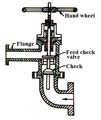
Fig. 25.6 Feed check valve
25.1.7 Steam stop valve
25.1.7.1 Function
It is fitted over the boiler in between the steam space and steam supply line. Its function is to regulate the steam supply from boiler to the steam line.
25.1.7.2 Construction and working
The construction of steam stop valve is as shown in fig 25.7. Its casing has a L-shaped steam flow passage. It consists of a valve and valve seat to stop or allow
the steam flow.
The valve is attached to a spindle and handle. Spindle passes through packing in the stuffing box to prevent leakage. The spindle has external threads in the top portion and moves in the internal threats of a fix nut. By rotating clockwise and anticlockwise the spindle and valve moves down and up thus closing or opening the valves.
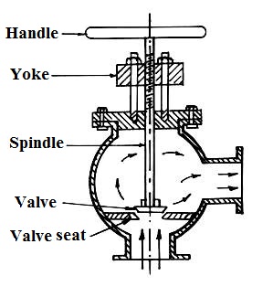
Fig. 25.7 Steam stop valve
25.2 Boiler Accessories
Boiler accessories are the components which are attached to the boiler (Not mounted on it) and are essentially for working of boiler and for increasing its efficiency. Various boiler accessories are discussed as below
25.2.1 Feed pump
Feed pump is placed nearby the boiler and is used to feed water to boiler working at a high pressure. The job of feed pump is not just put the water in the boiler but as boiler is working at high pressure, discharge pressure of feed pump must be sufficiently higher than this to push the water inside the boiler.
25.2.1.1 Construction & working
The feed pump used in boiler is of two
types (i) Reciprocating type (ii) Rotary type. Both these types are positive
displacement type to discharge against high pressure. The discharge pressure of
a single stage centrifugal pump is not high enough to overcome the high
pressure of boiler so multistage centrifugal pump is used as a boiler feed
pump.
In stationary low pressure boiler used in processing industries, a multistage centrifugal pump run by an electrical motor is more suitable. In multistage centrifugal pump, a number of centrifugal casing are so attached to each other that the impeller of each is mounted on the same shaft run by an electrical motor and discharge of 1st stage goes to 2nd stage and of 2nd to 3rd stage and so on. As shown in fig 25.8, in each stage the pressure of water goes on increasing and discharge pressure of final stage is so high as to overcome the internal pressure of boiler. Theses pumps have independent working and have smooth operation.
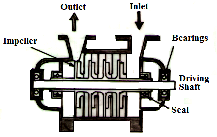
Fig. 25.8 Multistage centrifugal pumps
25.2.2 Economizer
25.2.2.1 Function
An economizer is a specially constructed heat exchanger for harnessing the heat energy of outgoing flue gases and utilizing it in preheating of boiler feed water. It saves the heat energy and so the fuel and decreases the operating cost of boiler—by increasing its thermal efficiency.
25.2.2.2 Construction & working
Economizers are of two types as (i) External type (ii) Internal type. The external type economizer is constructed and installed apart from the boiler and the flue gases from the boiler are directed to flow through it before escaping through chimney. A vertical tube external economizer is shown in fig 25.9

Fig. 25.9 External economizer
It is employed for boilers of medium pressure range. Here a number of vertical tubes made of cast iron are connected to common headers at the bottom and top. Feed water flow into the bottom header and then through the vertical tubes flow out from the top header. Hot flue gases escaping from the boiler are directed to flow across the outside surface of tubes thus indirectly heating the feed water flowing inside. To avoid deposit of soot over the tube surface, tubular scrapers are fitted over the tubes. These are operated by chain and pulley system and while moving up and down slowly scrap the soot over the wall of tubes and so increase the heat transfer rate. An internal tube economizer is fitted inside the boiler and is an integral part of it.
Advantages of Economizer
1. Stresses produced in the boiler material due to temperature difference of boiler material and feed water are reduced because of increase in feed water temperature.
2. Evaporative capacity of boiler increases as less heat will be required to generate steam if feed water temperature is already high due to preheating.
3. Overall efficiency of boiler increases because of more steam produced per kg of fuel burnt.
25.2.3 Air Pre-heater
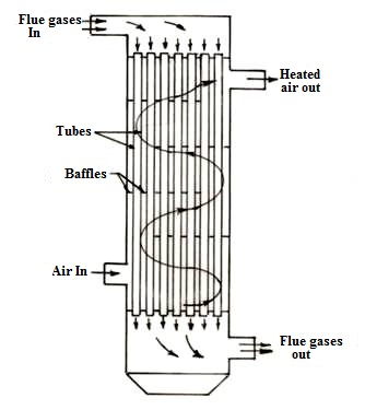
Fig. 25.10 Air Pre-heater (Tubular Type)
25.2.3.1 Function
The function of air pre-heater is to further utilize the heat of flue gases after coming out of economizer to preheat the air used in furnace or oil burner.
25.2.3.2 Construction
It is a plate type or tubular type or storage heat exchanger, in which flue gases pass through the tubes on one side of plate and air pass on other side. In storage type a rotor fitted with mesh or matrix alternatively come in the passage of flue gases and air thus exchanging heat. A tubular type air-heater is as shown in fig 25.10
25.2.4 Super heater
The function of super heater is to increase the temperature of steam beyond its saturation temperature. It is a type of heat exchanger. Hot flue gases coming out of burner are first directed through super heater before the boiler. The main advantage of superheating of steam comes in power plants, where steam is expanded through a turbine. But in a processing industry superheating is required only to avoid condensation in pipes. Thus super heater has less advantage or use in a processing industry and many times not used but not always.
25.3 Preventive Maintenance of Boilers
25.3.1 Daily check list
· Blow down and test low water cut off
· Blow down gauge glasses
· Blow down boiler
· Check boiler and system for leaks
· Check burner flame
25.3.2 Weekly checklist
· Check flame signal strength for both pilot and main
· Check pilot and main fuel valve shutoff valves closing
· Check igniter and burner operation
· Check level in chemical treatment tank
25.3.3 Monthly checklist
· Check boiler water treatment test results and adjust if necessary
· Lubricate motors and equipment bearings
· Check main fuel safety shut off valve for leakages
· Check low fire start interlock
· Check high pressure/temperature interlocks
· Check high and low pressure interlocks on gas train
· Manually lift safety valve by hand
25.3.4 Six-monthly checklist
· Inspect burner components
· Check flame failure system components
· Check piping and wiring of all interlocks and shut off valves
· Recaliberate all instruments, indicating and recording gauges
· Perform a slow drain test for low water cut off
· Check combustion control system
· Check oil atomizer nozzles and strainers
· Test boiler safety valve as per ASME standards
25.3.5 Annual checklist
· Perform the six monthly checks
· Check all equipment coils and diaphragm
· Perform a pilot turn down test
· Recondition or replace low water cut off assembly
· Check gas drip leg and gas strainer
· Clean boiler fireside
· Drain boiler open hand holes and manholes and clean water side
· Have boiler inspected by a competent & authorized boiler inspector
· Clean burner blower primary and secondary fans
· Replace all gaskets
· Leak test all fuel valves
· Test operation of all controls and safety devices
· Adjust combustion parameters for low and high fire conditions
· Retest and re certify boiler monitoring system