Module 11. Layout of steam pipe line
Lesson 27
STEAM PIPE LINE, FITTINGS, JOINTS, MATERIALS AND INSULATION
27.1 Introduction
We have already discussed the importance of steam as a safe and hygienic heating medium in food processing industries. Steam is a very efficient heat carrying medium as it carries heat in the form of its large latent heat. For example one kg water at 100°C carries an enthalpy equal to 419.1 kJ while dry saturated steam at 100°C carries an enthalpy equal to 2676 kJ. Steam is generated in a steam generator or boiler by burning of fuel. Steam generators with their mountings and accessories have already been discussed in previous lessons. After generation, steam has to be safely distributed to various points in the plant. This is done through a network of insulated pipe lines.
Steam pipe lines are joined together with any type of pipe joints. Some flexible joints are also necessary for bearing the thermal expansion of pipes and to save the pipe and other fittings from undue stress and strain. These joints are called expansion joints. To control the steam or condensate flow, through pipes, valves are also required. These control valves may be operated manually or automatically.
In most of the steam applications, electronically controlled pneumatic valves are used for flow and pressure control. These valves are always fitted with a bypass line having manual valves, so that steam flow may be carried out in case of faulty pneumatic valve. Flow metering is also done at some points with the help of flow meters. For the safety of steam pipes, joints, fittings and steam using equipment and their safeguard against blast due to higher pressure in steam distribution system, some kind of safety valves must be used.
As steam is a heat carrying medium and its temperature is sufficiently higher than outside temperature, it will lose its heat while flowing through steam distribution system. However effective insulation is provided over the steam pipes, valves and fittings, still the losses cannot be reduced to zero and reasonable amount of heat losses have to be taken into account, while calculating the steam consumption of equipment. On loosing heat in the pipe line network, some of the steam condenses there itself and this condensate has to be removed from the pipe line at strategic points. If this condensate is not removed properly, it may have serious consequences as hindering the steam flow by reducing the effective area of steam flow and also increasing the risk of water hammering. Water hammering produce disturbing noise and it may also cause blast producing threat to life and property. Thus the condensate must be removed strategically from appropriate points in the pipe line through steam trapping system. Faulty design of fitting points of steam trap may have serious concern with the safe and efficient use of steam in the plant.
Some other pipeline ancillaries like isolation valve, pressure reducing valves, check valves, strainers, separators, pressure gauges, temperature indicators, sight glasses, vacuum breakers etc are also required in the steam pipe distribution system.
The purpose of steam distribution system in the plant is to ensure the supply of steam of right quality and pressure to ‘steam using equipment’ in the right quantity.
27.2 Layout of Steam-Pipe Line Circuit
The purpose of steam pipe circuit is to carry the steam generated by steam generator at a given pressure and supply to each steam using equipment in accordance with its requirement regarding quantity, quality and pressure. In case of a pipe line used for liquid flow, the pressure difference at the inlet and exit points, is equal to sum total of various losses occurred throughout the pipe line as per Bernoulli’s theorem. But in case of steam flow, condensate is formed in the pipe line also due to heat loss by steam. Condensate has very less volume as compared to that of steam, so the formation of condensate also causes pressure drop along with pressure drop due to flow resistance. Quantity of condensate formed in the pipe line also effect the effective area of flow of steam and so affect its velocity and pressure drop. Thus theoretical analysis of steam flow through pipe line is somewhat difficult and its design is mostly based on experimental values of pressure drop, condensation rate etc through pipes available in the form of tables. However theoretical values of pressure loss or head loss in single phase flow through pipes is given by D’Arcy equation
![]()
Where hf = Head Loss due to friction (m), f = friction factor, L = Corrected Length of Pipe (m), u = Mean Flow Velocity (m/s), d = Pipe diameter (m)
Value of ‘f’ can be read from Moody’s Chart.
One more factor affecting the flow is that specific volume of steam does not remain constant and vary with variation of pressure.
Based on all the above mentioned factors and the quantity of steam flow rate required steam piping system is designed. A typical example of a basic steam pipe circuit is shown in figure 27.1. Initially there are one or more main pipes which carry steam from boiler to plant. From the steam mains smaller branch pipes carry steam to individual equipment. Branch pipes are always joined at the top of steam mains to avoid flow of condensate.
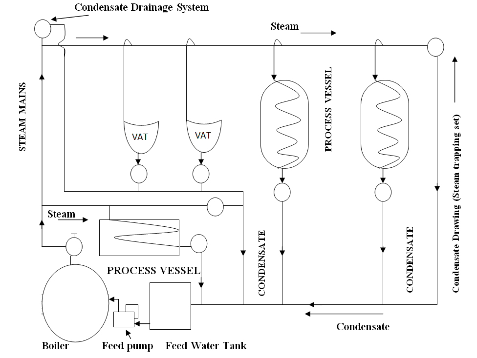
Fig. 27.1 Basic steam pipe circuit
When the boiler main valve is opened after a long shut down period, steam flows through cooler pipes and condensation rate is higher. Once the pipe has warmed up, condensation rate decreases. The resulting condensate collects in the bottom portion of pipe and carried in the direction of steam flow. A down slope normally of 100:1 is also given in the flow direction of steam to assist the condensate flow. Condensate collection points are provided at suitable intervals depending on quality of condensate and also any low lying point in the piping work. Condensate is collected through steam traps. This condensate however needs to be extracted from steam flow lines, but it is not waste and serve as boiler feed water. It decreases the demand of softening and preheating the feed water thus increases the energy efficiency. Therefore if possible this condensate is collected in a common condensate return line and fed directly to boiler through feed pump as shown in fig 27.1. In this way, steam circuit becomes a closed loop-circuit.
27.3 Steam pipe standards
There are a number of piping standards used around the world. One, API (American Problem Institute) standard are widely used. Here pipes are categorized in schedule numbers bearing a relation with pressure rating. There are eleven schedules starting from 5 through 10, 20, 30, 40, 60, 80 to 160. Higher is schedule number, higher is pressure rating, so higher is thickness of a given size pipe. Pipe size means their nominal diameter in mm the 40 mm, 100 mm etc so a 40 mm steam pipe will have different value, each of thickness, outside diameter and inside diameter for different schedule numbers. Pipes are normally flanged but in European standard threaded steel pipes are also used which are identified by different colour band as heavy, medium, or light etc. Red band is for heavy grade steel pipe and blue band is for medium grade steel pipe.
27.3.1 Pipe material
Steam pipes are commonly manufactured from carbon steel. For high temperature superheated steam mains, additional alloying elements such as chromium, molybdenum are added to improve strength and creep-resistance. Sometimes copper is also used as material of steam pipes in some applications.
27.4 Steam Pipe Line Fittings and Ancillaries
A typical steam pipe line from the steam mains to steam using equipment is shown here in figure 27.2

Fig. 27.2 Steam pipe line fittings
To carry out the different functions and to ensure the supply of right pressure, condensate free and right quantity of steam from steam mains to steam using equipment, various types of control valves, safety valves, steam separator, traps, strainers, condensate valves, air vents, pressure, temperature indicators etc are fitted in the steam line as shown in fig 27.2. These are explained briefly one by one as follows:
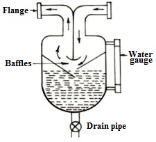
Fig. 27.3 Steam separator
27.4.1 Steam separator
Its function is to separate water particles from steam just before it is supplied to any processing equipment so that it gets only dry steam. A simple type of steam separator is one as shown in fig.27.3, in which steam pass on through baffle plates taking first downward and then upward flow. Due to this, heavy water particles, are collected at bottom and may be drained through a valve.
27.4.2 Steam flow meter
It is used to measure the value of steam flow rate and is installed in a main line or branch line going to a particular section or building.
27.4.3 Steam control valve
Automatic Steam control as per the process requirement is in itself a vast subject. Pneumatic steam control valves are fitted in the steam lines which are operated automatically by electronic controls or PLC system. Manually operated steam valves are also fitted in by pass to pneumatic valves. The working of a manually operated steam stop valve has already been discussed in lesson 25.
27.4.4 Safety valves
Safety valve is also fitted in the branch line connected to steam using equipment. This valve is set as per the maximum pressure rating of that particular equipment. In case the pressure exceeds beyond the maximum safe pressure, it release the steam and saves the steam line steam jacket and other fittings from bursting and damage. It is an essential safety fitting. Its working also has been already discussed in lesson 25.
27.4.5 Pressure reducing valves
Sometimes, if the pressure in steam mains remains higher and a low pressure steam is required in any particular application, a pressure reducing valve is fitted to reduce the pressure of steam going to that particular process equipment. However many a times, control valve also act as a pressure reducing valve by throttling of steam while passing through the narrow passage of valve.
27.4.6 Steam trap
Steam trap is a very important fitting of a steam distribution system. Steam traps are necessary to be fitted in the steam mains, steam header, branch lines and the lower end of steam jacket or coil of a process equipment to remove the condensate and air etc. collected at the lower end and to trap the live steam escaping with condensate. The discharging of condensate is allowed through an appropriate opening or valve but as soon as after removal of condensate, steam starts escaping, the opening is closed automatically by any of the methods, based on which steam traps are classified as:
(a) Thermostatic Steam Trap
(b) Mechanical Steam Trap
(c) Thermodynamic Steam Trap
27.4.6.1 Thermostatic steam trap
In this type of trap, there is a temperature sensing metal strip or liquid filled element as shown in fig. 27.4, which on higher temperature bends or expands and close the exit valve against its seat. The adjustment is done in such a way that when the thermostatic element is in contact with condensate whose temperature is less than that of steam, it keeps the exit valve of condensate in open position. But as soon as steam starts escaping, element’s temperature increases due to increased heat transfer in contact with steam and it bends or expends and close the exit valve thus preventing the outflow of live steam.
Thermostatic steam trap also helps in escaping of air at the startup as it remains open initially and closes only when exposed to high temperature of live steam.
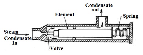
Fig. 27.4 Thermostatic steam trap
27.4.6.2 Mechanical steam trap
It operates by the movement of float, floating on condensate as shown in fig.27.5. Float operates the exit valve for condensate by upward or downward movement with the changing level of condensate in the trap. Its working is very simple. When condensate escapes, its level goes down and with that float also moves down and closes the exit valve thus trapping the steam.
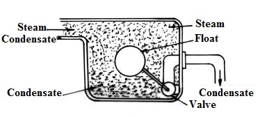
Fig. 27.5 Mechanical steam trap
27.4.6.3 Thermodynamic steam trap
It is operated by the difference of forced applied by the condensate and by steam to lift a disc operating the exit valve as shown in fig.27.6. Condensate is liquid and so heavy and exerts more force through a narrow hole as required to lift a disc and open the exit valve. But when condensate is escaped and steam starts coming, its force through narrow hole on the disc is not sufficient to keep the disc lifted up because steam has very high specific volume and so high velocity but less pressure energy. So the disc rests down and closes the exit hole and trap the steam.
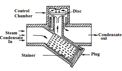
Fig. 27.6 Thermodynamic steam trap
27.4.7 Steam strainer
The purpose of strainer in steam pipe line is to arrest debris, rust, weld metal pieces etc and protecting the control valves, traps and other instruments fitted in the line. Two types of strainers are mostly used as y-tube strainer and basket type strainer. In both types, steam passes through cylindrical strainer, which does not permit debris to pass on. These strainers are also a source of condensate collection which should be removed from there, only by drain plug and not to be allowed to flow along steam. Steam strainers are fitted normally before the steam trap.
27.5 Steam Pipe Expansion and Support
We know that steam pipe undergoes thermal stress and their expansion or contraction takes place during full flow of steam and shut off period. Thus the steam lines must be supported on flexible supports and should be provided with suitable expansion joints to allow the expansion or contraction movement of steam pipe lines. The pipe work in itself also should be sufficiently flexible to accommodate the movement of components. For that the bends or loops are provided in the pipe line to absorb the movement as shown in fig.27.7. The supports are chair and roller type in which pipe rests on a horizontal roller which carry the weight of pipe and also allow sliding movements of pipe as shown in fig 27.8
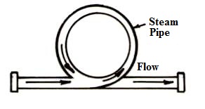
Fig. 27.7 (a)
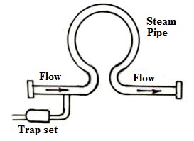
Fig. 27.7 (b)
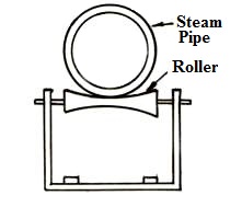
Fig. 27.8 Roller type support
Special type of expansion joints or bellows as shown in fig.27.9 are also available which allow both the linear and lateral movement of pipe.
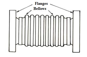
Fig.27.9 Expansion joint
27.6 Steam Pipes Insulation
To bear the high pressure and temperature of steam, steam pipes are made of carbon steel. If not insulated properly, the steam will lose a significant amount of its useful heat on the way to steam using equipment and will be direct loss of energy. So, the pipes must be insulated properly to increase the heating efficiency of steam system. Up to 90% of heat losses can be avoided by providing insulation. Insulation also enhances the safety as it conceals the extremely hot surface of metal pipes.
There is a variety of materials that can be used to insulate steam pipes such as fiberglass, neoprene foam, polyethylene, mineral wool, calcium silicate etc. Asbestos was also used in some older steam pipe system but now its use is discarded because it poses risk to life if its dust is breathed into lungs. The effectiveness of most of the insulation materials depend on minute air cells held in a matrix of insulation material. These air-cells may be destroyed if insulation absorbs moisture. So to prevent insulations getting moisture and also to impart strength to it, aluminum cladding is provided over insulation. Readymade insulation pieces in the shape of half cylinders are available for different size pipes which are placed on pipe and bound by high temperature tape. Then aluminum cladding is provided. Special shape insulation covers are available for other fittings also.