Module 13. Air compressor
Lesson 31
AIR COMPRESSORS
31.1 Introduction
An air compressor is a mechanical device which produces the compressed air i.e. which increases the pressure of air above the atmospheric pressure as per the requirement and stores it in a high pressure vessel. In air compressor, normal atmospheric air is sucked and compressed continuously. It can be run or derived by an electric motor, IC engine or steam engine etc. The high pressure air or compressed air has numerous applications in industry as well as in our daily life.
Some of the applications of compressed air are given as below:
(i) Dusting/cleaning in home, shops etc.
(ii) Inflation of tires.
(iii) Operating tools in factories.
(iv) Operating heavy drills, execrators etc.
(v) Boring and developing of tube wells.
(vi) Starting Diesel engines with air starter motor.
(vii) Operating brakes of buses, trucks or other heavy vehicles.
(viii) Operation of pneumatic valves in automated processing industries
(ix) Drying industry.
(x) Air conditioning.
31.2 Use of Air Compressor in Dairy Industry
Dairy Industry is a type of food processing industry, where milk is processed to produce a number of milk products. The process control is carried out by keeping the operating parameters like pressure, temperature, concentration etc., in optimum range by automatically controlling the flow rate of milk/ milk product, steam and cooling water or refrigerant etc. through pneumatic (air operated) valves. Many a times, some other type of automated mechanical movements are required to be carried out in a processing or packaging machine automatically for the purpose of process control. These movements are carried out precisely with the help of air-motors run by compressed air for example in a pouch filling and packing machine. Compressed air is also used in general dusting and cleaning purpose in a plant. Compressed air is also required in cleaning and drying of milk storage and processing equipment. Thus compressed air finds very important application in modern dairy processing plants and is an important utility
31.3 Classification of Air Compressor
Air compressor is actually an air pump just like a water pump, which pumps the air continuously from low pressure to high pressure. Air compressors may be classified on various basis as mentioned below. (Fig. 31.1)
31.3.1 On the basis of principle of working
A. Positive Displacement Type
B. Centrifugal Type
31.3.2 On the basis of number of stages
31.3.2.1 Single stage
When the compressor compresses the air straightway from atmospheric pressure to discharge pressure in a single stage is called a single stage compressor.
31.3.2.2 Multi stage
When the compressor compresses the air from atmospheric pressure to final discharge pressure in more than one step by using more than one single stages of compressor is called Multi-stage compressor. Here the discharge of first stage enters the suction side of next stage and so on until the air is discharged to required pressure of final stage.
31.4 Positive Displacement Type Compressor
In positive displacement type compressor, a moving mechanical component, displaces or compresses the air positively against high pressure. These are further of two types as discussed below:
31.4.1 Reciprocating compressor
It is called so because here an air tight component i.e. piston reciprocates continuously in its counterpart closed component i.e. cylinder. With the help of operation of automatic valves, piston sucks fresh air inside cylinder in one stroke called suction stroke and pushes or discharges it to high pressure air tank in the next discharge stroke. Thus piston is made to reciprocate with the help of a connecting rod and crankshaft rotated by an electric motor. The construction of a reciprocating air compressor is basically similar to an IC engine. Here also the basic components are same i.e. cylinder piston, connecting rod, crankshaft, cylinder head valves etc. One main difference is that the engine produces power but air compressor consumes power. A reciprocating air compressor is further classified as single acting or double acting based on that piston sucks and compress the air from one side only or from both the sides of piston like IC engine, compressor may also be single cylinder type or multi cylinder type. Multi cylinder compressor may also further be having many type of arrangements or designs like In-line or V-type etc.
31.4.2 Rotary compressor
In this compressor a rotating mechanical component displaces the air positively and continuously through the casing of air compressor in which it is rotating. By this rotating movement, air cavities are formed which move from one place to another place or which shrink continuously and compress the air. Based on the construction of casing, rotating part and principle of cavity movement, these are further classified as:
a) Roots Blower Compressor or Lobe Type Compressor
b) Sliding Vane Compressor
c) Screw Compressor
d) Spiral Compressor
31.5 Centrifugal Compressor
Centrifugal compressor is one which imparts rotational energy to air. This rotational energy is converted to centrifugal force by which the air flows against pressure in the discharge side. The rotating mechanical component which imparts rotational energy to air is called impeller. The impeller consists of curved vanes which facilitate the flow of air through it. The fixed vanes of diffuser in the centrifugal casing convert a part of this rotational energy of air into pressure energy and air is discharged against high pressure. The main components of centrifugal compressor are centrifugal casing, impeller, main shaft, diffuser, suction and discharge ports etc.
In a centrifugal compressor, the flow of air takes place through compressor in a direction normal to the axis of rotating shaft. But if the flow takes place parallel to the axis of main shaft, it is called axial flow compressor. Construction wise, centrifugal compressor can also be named as rotary compressor or a rotary compressor can be of both types as positive displacement type and centrifugal type.
31.6 Single Stage, Single Cylinder, Reciprocating Air Compressor
31.6.1 Construction
The basic construction is similar to as that of an IC engine i.e. there is cylinder, piston, connecting rod, crankshaft and suction and discharge valves etc as shown in (Fig. 31.1). The main shaft or crank shaft is rotated by some external prime over i.e. an IC engine or an electric motor. The crank with the help of connecting rod gives the reciprocating motion to piston in the cylinder. Where the piston moves away from the closed end of cylinder, where the suction and delivery valves are located, it sucks the atmosphere air in the cylinder through suction valve operated by pressure difference. During suction stroke, delivery valve which connects the cylinder to compressed air tank remain closed due to high pressure in the tank and low pressure in the cylinder but the suction valve remains open.
After the suction stroke, when the motion of piston is reversed, the volume in cylinder starts decreasing thus increasing the pressure. Now the suction valve remains closed. When the pressure reaches above a value as in compressed air tank, delivery valve opens and this high pressure air is discharged in the air tank for the rest of stroke. The cycle on which air compressor works is shown on PV diagram in fig 31.2.
The compression cycle 1-2-3-4 has four processes as:
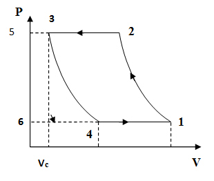
Fig. 31.2 P-V diagram of single stage reciprocating air-compressor
V1 = Total volume of Cylinder
VC = Clearance volume of Cylinder
V1 – VC = Swept Volume (VS)
V1 − V4 = Effective Swept Volume
31.6.2 Working
1-2: Pure-compression
This process is most important in the overall working of a compressor. During this process, both suction and discharge valve remain closed and compressor acts as a closed system. On the upwards movement of piston from BDC volume of air inside the cylinder shrinks and so pressure rises. The compression may happen theoretically as any of the isentropic, isothermal or polytropic processes. In actual compressor it is always a polytropic process and try is made to keep it as close to isothermal process as possible by external cooling. Piston work is least in case of isothermal compression.
2-3: Compressed air discharge
When the pressure in the cylinder reaches to a value of pressure in compressed air vessel, somewhere in between the stroke of piston, discharge valve opens and compression becomes an open system. On further upward movement of piston, compressed air is simply discharged to compressed air tank through the discharge valve. This process ends when the piston reaches to the top end position, TDC and stroke is completed. During this process compressor acts like a pump which discharges the compressed air but does not compress it further.
3-4: Expansion of air trapped in clearance volume
This process starts as soon as the piston starts moving down towards BDC and cylinder volume starts increasing. Due to increase in volume pressure falls down and discharge valve close but some high pressure air remains in the clearance volume which could not be discharged. On downward movement of piston, this clearance volume air expands polytropically or isothermally or isentropically doing some work on the piston. When somewhere in between the downward stroke of piston during expansion, pressure falls below the outside normal air pressure, suction valve opens and expansion process ends. During this process compressor acts as a closed system. This process is reverse of compression process 1-2 and it also takes place for a part of the stroke of piston. Due to this process the effective suction of air is reduced and volumetric efficiency becomes less than 1.
4-1: Suction of air
On further downward movement of piston after opening of suction valve, atmospheric air is sucked in the cylinder until the piston reaches to bottom dead centre (BDC). In this process, compressor acts as an open system and fresh mass of air is sucked from atmosphere. At the end of this stroke cycle completes. The theoretical work consumed by compressor during one cycle is given by area of enclosed cycle 1-2-3-4.
In this way, when the piston is reciprocated continuously in the cylinder by rotating the crankshaft with the help of an electric motor, it completes one working cycle in two strokes of piston or one revolution of crankshaft. The expansion of high pressure air, trapped in the clearance volume (C.V.) in the previous stroke, and suction of fresh air from atmosphere takes place during downward stroke of piston from TDC to BDC, Then compression of air and its discharge to air tank take place during upward stroke of piston from BDC to TDC.
With the running of compressor, normal atmospheric air is continuously compressed and accumulated in high pressure air tank. The construction of suction valve and discharge valve is geometrically similar but they act in the opposite direction under the action of two forces, one is spring force and other is force due to pressure difference. Normally the spring keeps the suction valve pressed on its seat in upward direction in closed position and it opens against spring force only when vacuum is created inside the cylinder during suction stroke. Conversely the spring keep the discharge valve pressed on its seat in downward direction in closed position and it opens against spring force only when pressure in cylinder is higher than that in discharge port or air tank. Suction valve opening is connected to an air filter placed in open atmosphere. Discharge valve opening is connected to closed discharge port connected to air tank on other side. Reciprocating air compressor is a similar but simpler machine than an I.C. engine. Similarity exists only in basic design and construction but purpose of both are altogether different.
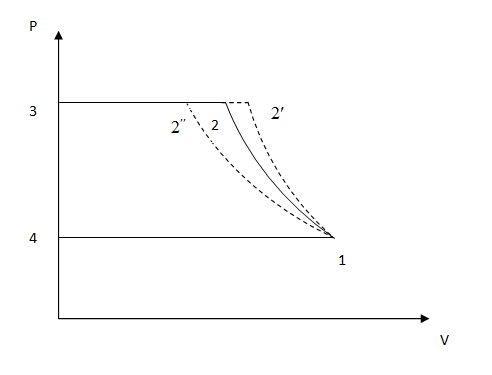
31.7 Comparison of Adiabatic, Polytropic and Isothermal Compression
We have discussed the working of an air compressor in the previous article. The working cycle is shown on P-V chart in fig 31.2 and work required by compressor in one cycle is given by area of cycle 1-2-3-4 on P-V chart. If the compressor is considered as an open system then the flow work is given by compression work minus expansion work. This work depends on the pressure ratio i.e. the ratio of discharge pressure to suction pressure and the type of compression process. The compression process 1-2 is a non-flow process and may be any of the isothermal, adiabatic and polytropic processes. We know that isothermal compression line 1-2” is more flat than an adiabatic and polytropic line which depends on the value of polytropic index ‘n’. The compression index in isothermal compression is ‘1’ and in adiabatic compression is ‘γ’. If n < γ, polytropic compression line will come in between isothermal and adiabatic line and if n > γ it will be more steep than adiabatic line. From the fig 31.3, it is clear that work will be least in most flat curve i.e. in isothermal compression. In adiabatic compression, work will be maximum. However, an actual process with sufficient cooling of compressor will be polytropic and fall in between the two curves. More and more cooling is used, more and more it will be towards isothermal line and work required will minimize. It shows the importance of external cooling in air compressor.
Small air compressor is generally air-cooled for which the fins are provided on the cylinder walls while large size air compressors are water cooled for which water jackets are provided around the compressor’s cylinder and cylinder head.
![]() :
Polytropic Compression
:
Polytropic Compression
![]() :
Adiabatic Compression
:
Adiabatic Compression
![]() :
Isothermal Compression
:
Isothermal Compression
Fig. 31.3 Single stage Air Compressor with zero clearance volume
In another way, it can be concluded that, in case of an isothermal compression i.e. compression without any rise in temperature, compressor has to work against the rise in pressure of air or gas due to shrinkage of volume only and so work is least. In case of isentropic compression, compressor has to work against the rise in pressure due to shrinkage of volume of air or gas and also due to rise in temperature thus more work is required. If some cooling is done, temperature rise will be less and so pressure rise will also be less thus lesser work will be required. In all these three cases, we are talking about the work required against compression of gas only without considering any internal or external friction and other losses. Considering all these losses, the actual work requirement will further increase. Overall, it can be concluded that work required in compression can be minimized by choosing such design of compressor, where friction and other losses are least and cooling is more and more effective.
31.8 Various Terms & Efficiencies Used in Air-Compressor
31.8.1 Free Air Delivery: (F.A.D.)
It is the volume flow rate of compressor expressed in m3/min as reduced to intake pressure and temperature.
31.8.2 Volumetric efficiency
It is the ratio of volume of free air delivered per stroke to the swept volume of compressor. As some part of swept volume is used up in the expansion of clearance volume gas, volumetric efficiency is always less than one. Volumetric efficiency is also reduced due to resistance offered by suction valve and heating up of suction air in the compressor.
31.8.3 Isothermal efficiency
It is the ratio of work required by compressor in case of isothermal compression in an air compressor to the actual indicated work of compression. Indicated work of compression means the work represented by indicator P-V diagram of compressor.
31.8.4 Isentropic efficiency
It is the ratio of isentropic work of a compressor i.e. work consumed considering isentropic compressor to the actual work required by compression. This term is mostly used in refrigerant compressor.
31.8.5 Mechanical efficiency
It is the ratio of indicated power of compressor to the actual shaft power of compressor. Shaft power of compressor means power required to be given to its driving shaft. It accounts for the loss of power due to friction in moving parts.
31.8.6 Overall isothermal efficiency
It is the ratio of compression work in case of isothermal compression to the actual work required by the compressor.
31.8.7 Clearance ratio
It is the ratio of clearance volume
to the total swept volume of an air compressor. It is denoted as K or C.
![]()
31.8.8 Pressure ratio
It is the ratio of discharge pressure to suction pressure of a compressor or one stage of a multistage compressor. In general, in a compressor, the compression process is polytrophic and it lies in between isothermal and isentropic, if effective cooling is done in compressor. In this case efficiency of compressor (Ratio of theoretical work to actual work) used is isothermal efficiency. Otherwise in real conditions, the actual work is even more than the isentropic work due to friction and other losses and efficiency used is isentropic efficiency.
31.9 Multistage Compression
As mentioned upto now is the single stage compression i.e. the pressure is raised from atmosphere to the required value in one stage. But when the requirement is of very high pressure, single stage compression has some disadvantages as mentioned below:
1) With the increase in delivery pressure, the high pressure air remained in clearance volume takes more part of piston stroke to expand upto suction pressure thus decreasing the effective swept volume and hence the mass flow rate through compressor. It is clear from figure 31.4 that if the delivery pressure is too high, there may not be any discharge of air and the compression and expansion processes 1-2 or 2-1 may takes place in full strokes of piston. In that case valve will not operate and delivery of air would become zero.
2) With the increase in delivery pressure delivery temperature also increases which if not required is a dual energy loss.
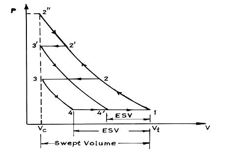
Fig. 31.4 Compression cycles with different values of delivery pressure
3) High delivery pressure will also require heavy working parts and more unbalancing.
The only solution to this problem is to increase the delivery pressure not in single stage but in multistage. First, the atmosphere air is compressed to a reasonable intermediate pressure level in the first stage and is delivered as suction of 2nd stage where the pressure is further increased reasonably and so on until the final pressure is reached. There may be two, three or more stages depending on the delivery pressure required. Between the stages, the air may be cooled so as to keep the overall compression curve close to isothermal curve thus to decrease the compression work also. The combined compression cycle of multistage compressor is shown in fig 31.5
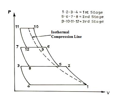
Fig. 31.5 Three stage compression cycle
In this way the multistage compression has various advantages over single stage as mentioned below:
31.9.1 Advantages of multistage compression
· The air can be cooled at intermediate pressure between the stages of compression, thus decreasing the work required for next stage. Hence, the power required to drive a multistage compressor is less than that required for a single stage compressor delivering the same quantity of air at the same delivery pressure.
· Multistage compressors have better mechanical balance. So lighter flywheel is required.
· The pressure and temperature range may be kept within desirable limits which results in
i). Reduced losses due to air leakage
ii). Improved lubrication
iii). Improved volumetric efficiency
· For higher delivery pressure, in a single stage compressor, cylinder, piston and other moving parts must be robust enough to withstand the higher load. However in multistage compressor, the low pressure cylinder may be lighter in construction.
· The size of different stages of compressor may be adjusted and designed independently depending on volume of air handled in different pressure range.
Disadvantages
The multistage compressor with intercoolers is more expensive in initial cost than a single stage, compressor of same capacity, but its running cost is less.