Module 6. Process control and automation
Lesson 16
DAIRY PROCESS MODELLING AND SIMULATION
16.1 Introduction
This lesson introduces the concept of process modelling and simulation of dairy products, application of software packages such as SCADA, INTELLUTION, CAD and CAM for product design and manufacturing. These topics will be useful for students to develop an idea about advancement taken places in dairy industry with respect to design and manufacturing of high quality dairy products.
16.2 Process Modelling
Modelling in dairy and food science helps in prediction of food materials’ behaviour in varying product and process conditions. This involves data collection, analysis, interpretation and mathematical modelling. Use of computers is prevailed to run large programs for the modelling purpose. The conceptual models are then used to perform quantitative analyses and predict behaviour of food material. Food process modelling requires study of the inherent/naturally occurring processes, processes applied to the food product and also of the processes occurring in model food systems as a response to its quality. The applications of the process modelling cover production, processing and storage of food products.
16.3 Fundamentals of Process modelling
Two approaches of process modelling are used, i.e. deductive and inductive.
16.3.1 Deductive modelling
In order to solve complex problems one has to decompose the complex process into its constituent processes, then study them individually, develop their models and combine their parameters to develop complete process models. The deductive modelling of food processing therefore, starts with the general laws of (chemical) physics, and uses them to build realistic mathematical models of food processing operations. The models for the individual processes are deduced from existing theories, principles and fundamentals. Deductive approach utilises principle of ‘inference from general to particular’. Advantages of deductive models are:
1. Reusable and possibility of parameter transfer
2. Widely applicable within the space of variables and systems described by the model
3. Involves basic fundamentals of food and related science
4. If model is valid on a simple system it can serve as a tool for computational exercise to adapt it to different processing conditions and more complex product geometry.
Applications of deductive modelling in dairy and food science include;
1. Process optimization: this involves modelling and simulation of all processing steps starting from milk production, processing, packaging, storage and handling. Some processes are modelled realistically; however, others are based on assumptions and theoretical considerations. The process optimization has to be governed by integrated approach which involves shelf life as well as sensory aspects of the food products. Thus it helps in prediction of keeping quality, shelf life, microbial growth, chemical reactions and phase changes.
2. Modelling keeping quality and shelf life of foods: Optimizing the drying or freezing operations and shelf life estimation of the food stuff considering rates of various deteriorative changes helps in modelling keeping quality and shelf life.
3. Studies on migration of microbial metabolites into the food product.
4. Studying the effect of food microstructure and the microscopic water distribution on survival of micro-organisms.
5. Modelling of flavour release from the food materials: This predicts mathematically the effect of varying food composition, food structure and mastication behaviour on the perceived time intensity flavour release profile.
16.3.2 Inductive or empirical modelling
Sometimes decomposition of the complex problems and processes result in more complicated forms which are not possible to be studied through fundamental approaches. Similarly if there is no or a little information available about the processes then inductive/ empirical modelling is preferred. The term inductive refers to ‘inference of the general law from particular instances’. Inductive modelling is typically data driven and requires minimal knowledge of the products or processes involved. This involves plenty of data collections and its analysis by fitting statistical models using tools such as regression and correlation. In every step an additional parameter is added to the objective function and the response is statistically analysed to see its significance. The resulting model converts model inputs into outputs and is often referred to as a ‘black box’ as there is no relation whatsoever with the real underlying mechanism.
Advantages:
· Models can be developed relatively quickly
· Show good results even when there is insufficient understanding of the processes involved
Disadvantages:
· Not be able to increase the understanding or generate new knowledge on the underlying mechanism.
16.3.3 Kinetic modelling
Kinetic modelling is useful from two perspectives: one, changes in physical-chemical, biochemical and microbiological reactions that occur during processing as also storage lead to loss of quality of the processed dairy foods. Kinetic modelling allows us to describe these changes as a function of processing variables and storage time-temperature so as to ascertain the rates of progress of these reactions and establish quantatively the progress of these reactions. To accomplish these tasks, understanding of classical concept of thermodynamics and kinetics are necessary.
Reaction kinetics: Kinetic evaluation of reactions involves the study of rates and mechanisms by which one chemical compound converts to another. Kinetic Equation of nth order is:
• Simplified
Zero order kinetic eq. (n=0): ![]()
• First
Order Kinetic eq. (n=1):
![]()
• Second
Order Kinetic eq. (n=2):
![]()
The rate constant is
generally temperature dependent and their relationship can be
modeled
as:
![]()
Where, R is universal gas constant, T is temperature in Kelvin, Ea is activation energy (j/mol), k0 is Arrhenius constant
Simplified form of above
equation is:
![]()
16.3.4 Heat and mass transfer modeling
Heat and mass transfer processes are the most common physical phenomena that occur during processing of foods. As a result several important variables such as the temperature and the moisture concentration inside the food depend on time as well as on their position inside the food system. Several of the product properties and quality indices of foods viz., microbial load, nutritional value, texture and organoleptic quality, are affected by these variables. An example of such a situation is very common processing intervention: thermal processing which may include retort processing or UHT sterilization. In both these processes, temperature of the boundary layer is likely to be higher than that at the centre of the can and therefore the dynamics of spore destruction will be different at the boundary and the centre of the can. The heat processing consideration may have to be designed keeping in mind the slowest heating point in the can. The famous Fourier equation considers only heat conduction processes in which heat is transported by molecular diffusion processes. Therefore the assumption is that the heat conduction in transient heat conduction in an isotropic object Ω with boundary ᴦ is governed by the following Fourier equation.
![]() Ω
Ω
Where,
ρ = density (kgm-3)
c= heat capacity (Jkg-1oC-1)
k=thermal conductivity (Wm-1oC-1)
Q=volumetric heat generation (Wm-3)
T= temperature (oC)
t= time (s)
The thermo physical parameters k, ρ and c may be
temperature dependent and therefore the problem becomes nonlinear. In general,
both the heat capacity and the density can be calculated with sufficient
accuracy but the models for the thermal conductivity require some assumptions
to be made with respect to the direction of heat flow. In conventional thermal
processing conditions, the heat generation Q is zero. However, in the case of ohmic or volumetric heating like microwave and ohmic heating, Q is the driving force of the heat transfer.
The modelling of these techniques is a very active research area
The phenomena of diffusion also occur during the
transport of water etc in the food system and are governed by Fick’s second law of diffusion.
![]() Ω
Ω
Where,
Ca = molar concentration of
component a (mol m-3)
Da = mass diffusion coefficient of component
a (m2s-1)
ra = rate of production of component a (mol m-3s-1)
T= time (s)
The above equation is valid only for diffusion in solids
or stationary liquids with the assumptions of constant density ρ and zero
mass velocity encountered in pure diffusion of a single species with negligible
changes in the total density. For other conditions, more complex transport
equations may be used. Da is not
constant but depends on temperature and the concentration of the components in
the mixture. ra
depends on the metabolic activity of the product, which is a function of
temperature and composition. In liquids, transport of heat and mass is much
more complicated than in solid foods, as besides diffusion also convective
transport of liquid particles may take place. Therefore different models and
mathematical considerations may have to be used for such situations. Many
heat transfer processes in food operations may also involve turbulent flow of
water. Turbulence enhances heat transfer rates considerably and therefore
turbulence should be incorporated in the models. Software tools are available
for modelling heat and mass transfer problems. The reliability of the numerical
solution, however, largely depends on the availability of suitable thermo
physical properties and the complexity of the governing models.
16.4 Simulation
Simulation
or mathematical simulation refers to a mathematical model that permits us to
work out a reasonable approximation of the corresponding real-life system. It
is used as a powerful tool in food processing applications for understanding
the behaviour of complex interactive systems, predicting operation results,
developing process control systems or optimizing the performance of a system.
Mathematical aspect of simulation has been made much easy after the advent of
computers. Using computers one can go from a spreadsheet where a model is built
from scratch to different types of available software packages. The packages to
model processes using computational methods are made of a block of generic
models of unit operations and balance equations and a block of physical
properties of the materials being processed. The two blocks interact to
describe changes along a flow description of the process.
The steps
involved in building a process simulation model are as under:
·
Define the problems
·
Identify the objectives
·
Understand the system and collect data
·
Select software
·
Draw process flow diagram
·
Create a rough model
·
Verify and validate the
initial results
·
Refine the model
·
Modify the base model with
alternatives
·
Analyze results and draw
conclusions
Some of the
important software systems used in process modelling and simulation studies is:
16.4.1 Supervisory control and data acquisition
(SCADA)
Supervisory
Control and Data Acquisition (SCADA) system is a type of industrial control
system for supervisory control and data acquisition of industrial processes. It
is a computer software package which is interfaced with hardware system through
PLCs to monitor and control wide range of industrial activities, infrastructure
and processes. It gathers and analyzes real time data to monitor and control a
plant or equipment in industries at supervisory level only. Some important
features of SCADA systems are:
·
Dynamic process Graphic
·
Alarm summery and history
·
Real time trend
·
Historical time trend
·
Security (Application
Security)
·
Data base connectivity
·
Device connectivity
·
Recipe management
SCADA
system consists of following subsystems:
1.
Human-machine interface
(HMI) - presents processed data to the plant operator enabling him to control
the process. Frequently, it refers existing SCADA databases and provides
relevant information to the operator for necessary action e.g. maintenance
schedule, trouble shooting, particulars of the instruments etc. the HMI
presents information generally in the form of graphical/pictorial/mimic
diagrams, process flow charts which are interactive in nature.
2.
Supervisory system/master
station (computer) - receives digital signal and sends commands to the process
controller. With the help of servers and software, it communicates with field
instruments i.e. Remote terminal units (RTU)/PLC and the HMI softwares.
3.
Remote terminal units –
converts analogue signal to digital one and sends it
to computer. It connects computer physically to the instruments.
4.
Programmable logical
controller - it also performs control actions by actuating feedback control
loop
5.
Network connecting various
RTU/PLC to the supervisory system- it utilizes both wired and radio
connections. Remote management of SCADA system is known as telemetry. SCADA
protocols are very compact.
6.
Processes and instruments
The role of SCADA system in controlling process is
explained through a diagram given below (fig. 16.1, Source:
http://en.wikipedia.org/wiki/SCADA). The SCADA system reads the measured flow
and the level in the tank and sends the set points (given by human operator) to
the PLCs. PLC1 compares the measured flow to the setpoint,
controls the pump speed as required to match flow to the set point and the PLC2
controls the flow control valve to match the level to the setpoint.
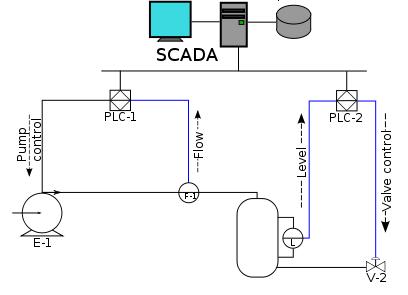
Fig. 16.1 Schematic
overview of SCADA system
16.4.2 Intellution
Intellution Inc. is a company which was founded
in 1980 with the aim to develop and supply software for industrial automation
and very soon, it become the leader in industrial automation software. It
developed and supplied the software under brand name Intellution
which, provides a software platform that collects, distributes, controls and
visually presents information from the plant floor throughout the enterprise,
supplying customers with scalable solutions. In 2002, GE Fanuc International,
Inc. purchased this company and recently released a new version of Intellution software named as Intellution
iFIX 5.5 with following additional capabilities and
features:
· Flexibility and reliability of connecting and
presenting data
· Best-in-class information analysis, real-time data
management and control with enhanced full-featured SCADA solution
·
Enables
faster, better intelligent control, and visibility into plant operations
·
Offers open
architecture, highly scalable and distributed networking model
· Scalability from isolated sensor to company-wide
integration
· Adherence to industry standards for improved
consistency, quality & compliance
·
Completely hardware independent
·
E-signature
functionality
· User-friendly interface
· Provision for developing and integrating new modules
using VBA Scripting and .NET
16.4.3 CAD and CAM in dairy industry
Computer-aided
design (CAD) and Computer-aided manufacturing (CAM) is a concept of using
suitable computer application software for designing, analyzing and
manufacturing the product. The nature and use of this software is relative to
what is being designed and manufactured. Formally, the efforts for developing
specialized CAD/CAM software were started in piecemeal at different places for
solving problems related to drafting, testing of designs by simulation, flow of
design data directly to the manufacturing process, etc. These developments
were pioneered by the General Motors Research Laboratories in early 1960s.
During early 1970s, the large scale production of electronic chips and
microprocessors has made powerful computers affordable at low prices to all.
This leads to development of more sophisticated CAD/ CAM software with advanced
features for designing and manufacturing products.
Computer-aided
design is the use of computers to assist in drafting, creation, communication, analyses, and optimization of 2D design or 3D models
for a product or components of a product. The design
of computer models is stored in computer files in form of geometrical
parameters using either vector based graphics or raster graphics. Design of a
product can be visualized from different angles on computer screens in two or
three dimensional representations and the parameters of the product can be
changed if required. The design can be tested and evaluated (e.g., physical
shape, size and volume, aesthetic, attributes, fluid dynamics, material suitability,
conductivity, etc.) by simulating with real-world conditions.
Initially,
the CAD systems were used for by electronic and mechanical engineering
industries for designing machines (say cars, airplanes, etc.) to improve the
quality of designs. But, now days CAD applications are used almost in all
fields such as civil engineering, garment design and production, food
industries, oil industry, etc. In food and dairy industry, CAD software enables
the manufacturers to design and develop novel food products of high quality at
reasonable prices. This covers all areas of product
development, from idea generation and research, investigating the functionality
and interactivity of different ingredients, producing manufacturing flow-charts
to assess food safety issues, knowledge based systems for food legislation and
innovative imaging systems for product quality and fault diagnostic purposes,
study of shelf life, etc. CAD system offer number of advantages such as:
·
Easy modification in design
· zooming to magnify certain elements of a model to
facilitate further inspection
·
3D models give the feeling
of real objects
·
Simulation by changing the
parameter values
·
Increases the productivity
of designers
·
Improve the quality of
design
·
Improve communications
through documentation
·
Create a database for
manufacturing.
Computer-aided
manufacturing is the use of computer to assist in manufacturing process by
controlling machine tools and related machinery automatically in the production
of components. In broad sense this term is used when one or more manufacturing
processes such as process control, robotics, measuring,
monitoring and controlling production are carried out at one time aided by a
computer. CAM uses 2D or 3D design data of components generated by CAD software
in geometrical coded form to control the computer numerical control (CNC)
machines automatically for manufacturing of components. This system differ from
older forms of numerical control (NC) in which, design data are encoded
mechanically. Main purpose of CAM is to monitor and control different processes
more precisely during manufacturing process to produce consistent and high
quality products at faster speed by minimizing the waste and energy
consumption.
Generally
the CAM systems were used by mechanical engineering industries. Because of its
potential uses, it is being used extensively in other industries also including
dairy and food industries. In diary and food industries, CAM systems are linked
to manufacturing lines monitoring and controlling manufacture to produce
consistent and high quality end products. For example, ‘dedicated control
systems’ monitor single unit operations, e.g. controlling the temperature of a
heat exchanger; they do not share the information with other computers.
However, ‘centralised control systems’ monitor and control complete operations
throughout manufacture; providing feedback about the entire process, e.g. milk
processing plant, fish finger production. Other applications of CAM include
production line robots deboning meat, decorating cakes, picking mushrooms and
packaging chocolates. A few advantages of CAM within the dairy and food
industry are:
· Reduced food wastage through efficient manufacture;
· Improved product consistency;
· Avoidance of downtime;
· Reduction in overheads, e.g. labour costs;
· Increased production capacity;
· No fatigue from repetitive manufacturing demands;
· Improved food safety and hygiene standards;
· Enhanced quality control.
The term
CAD/CAM in combination implies to a system that can be used both for
designing a product and for controlling manufacturing processes. CAD/CAM is
highly integrated system since both CAD and CAM are computer-based methods and
share numerical information of design data directly from CAD designs to control
manufacturing of the products. The integration of CAD/CAM gave the designer
much more direct control over the production process and created the
possibility of completely integrated design and manufacturing processes within
short duration.