Module 1. Alternating and direct current: fundamentals
Lesson 1
INTRODUCTION TO CIRCUITS
1.1 Introduction
Electrical engineering is a field of engineering that generally deals with the study and application of electricity, electronics and electromagnetism. Electrical energy is an important utility in a dairy processing plant for operating the equipments, instruments, control systems etc. Electrical engineering as a subject will give an understanding of A.C. fundamentals, A.C. circuits, transformers, alternators, motors, electrical measuring instruments and electrical power economics.
1.2 Important Terms
1.2.1 Electricity
Electricity is a form of energy which involves flow of electrons in a closed circuit to do work.
1.2.2 Electric current (I)
Flow of electron in an electric circuit is called electric current (I) and its unit is ampere (A).
1.2.3 Potential difference
When two bodies are changed to different electric potential, these exists a potential difference between the two bodies. Unit: Volt (v)
1.2.4 Resistance
The opposition offered to flow of electrons or current by a conductor / material is known as resistance. Unit: Ohm (Ω)
1.3 Law of Resistance
The resistance of a wire depends on the following function:
(a) Resistance (R) is directly proportional to the length of wire (L).
R ∝ L
(b) Resistance (R) is inversely proportional to the cross sectional area of wire (a).
R ∝ 1/a
(c) Resistance (R) depends on the temperature of the conducting wire.
(d) Resistance (R) depends on the atomic structure of the material.
1.3.1. Ohm’s law
Ohm’s law states that the current (I) flowing between two points in a circuit is directly proportional to the potential difference (V). This condition is applicable when temperature is constant.
I ∝ V
![]()
V = IR
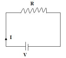
Fig. 1.1 Electric circuit
Numerical:
1. Calculate the current flowing in a circuit if voltage applied by the battery is 12 V and R = 5Ω.
Solution
V = IR
I = V/R
= 12/5
= 2.4 A
2. Calculate the current flowing in a A.C circuit at 220 V. Take value of R = 100 Ω.
Solution
V = IR
I = V/R
= 220/100
= 2.2 A
1.3.2 Effect of temperature on resistance
The value of resistance (RT) at any temperature T°C is given as:
RT = Ro(1+arT)
RT = Resistance at temperature T , Ohm
R0 = Resistance at 0°C,Ohm
ar = Temperature co-efficient of resistance at 0°C.
1.4 Electrical Circuit
The electrical circuit can be kindly classified as:
a) D.C. Circuit
b) A.C. Circuit. (will be covered in Module 2)
1.5 D.C. Circuits
A circuit based on direct current (D.C.) is known as D.C. circuit. Circuits can further be classified as:
· Series circuit
· Parallel circuit
· Series parallel circuit.
1.5.1 Series circuit
A circuit in which load (resistors) are connected in series so that same current flows through them is called series circuit.
Here three resistance R1 ,R2 & R3 are connected in series across a voltage of V volts.
Let V1 , V2 & V3 be the voltage across resistor R1 ,R2 & R3 resistivity.
![]()
![]()
Where
![]()
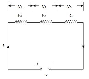
Fig. 1.2 Series circuit
1.5.2 Parallel circuit
A circuit in which load (register) are connected in parallel so that different current through them is called parallel circuit.

Fig. 1.3 Parallel circuit
Here three resistances I1, I2and I3 are connected in parallel across supply voltage of V volt. Note that the voltage V across each resister in same. The current flowing through R1, R2 and R3 are I1, I2 and I3 respectively.
![]()
Or
![]()
![]()
![]()
Where
R = Total resistance
![]()
![]()
![]()
![]()
Similarly
![]()
![]()
1.6 Kirchhoff’s Laws
1.6.1 First law: kirchhoff’s current law (KCL)
The algebraic sum total of all the currents (I1, I2, I3,….In) meeting at a point is zero.
![]()
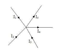
Fig. 1.4 Currents at a point
Taking incoming current at a point as +ve and outgoing current as –ve.
![]()
Or
![]()
1.6.2 Second law: kirchhoff’s voltage law (KVL)
(Also known as Kirchhoff’s mesh law)
The algebraic sum total of all the emf and all the voltage drops is zero in a closed circuit
or mesh.
![]()
Rules for algebraic sum:
· Rise in potential is considered +ve and fall in potential is considered –ve
· Taking following circuit as example
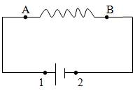
Fig. 1.5 Electric circuit
Voltage drop
· Tracing branch from A to B. V is negative (-v) i.e. fall is potential
· Tracing branch from B to A. V is positive
Emf
· Tracing branch from 1 to 2 E is negative
· Tracing branch from 2 to 1 E is positive
1.7 Superposition Theorem
The superposition theorem for electrical circuits states that for a linear system having two emf source in any branch of a bilateral linear circuit, the current flowing through any section is the algebraic sum of all the currents caused by each independent emf source acting alone, while all other independent sources are replaced by their internal resistances. Consider a circuit (Fig. 1.6) with two emf source.
Let r1 and r2 be internal resistance of emf source E1 and E2. Applying superposition theorem to the given electrical circuit:
· Case 1: considering first emf source E1 (Fig. 1.7). E2 is replaced by the internal resistance r2.
· Case 1: considering second emf source E2 (Fig. 1.8). E1 is replaced by the internal resistance r1.
Considering Fig. 1.6-1.8, the currents in different branches can be given as:
I1 = I1’ – I1’’
I2 = I2’ – I2’’
I3 = I3’ + I3’’

Fig. 1.6 Electric circuit with two emf source
Fig. 1.7 Electric circuit considering first emf source

Fig. 1.8 Electric circuit considering second emf source
1.8 Numerical
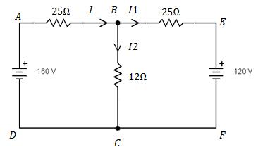
1. For the circuit shown below calculate the current and power in 12 Ω resistor.
Solution
For mesh A B C D A applying K V L
- 25 (I1 + I2) – 12 I2 + 160 = 0
- 25 I1 – 37 I2 + 160 = 0
25 I1 + 37 I2 = 160 ......... (1)
For mesh B E F C B Applying K V L
10 I1 + 12 I2 - 120 = 0
- 10 I1 + 12 I2 = 120
Multiplying above equation by 2.5
- 25 I1 + 30 I2 = 300 ......... (2)
Adding equ (1) & (2)
(25 I1 + 37 I2 = 160) + ( - 25 I1 + 30 I2 = 300) = 67 I2 – 460
67 I2 = 460
I2 = 6.86 A
Power p = I22 R2
P = 6.862 × 12
= 564.7 w
2. Find the branch current by superposition theorem in the following circuit.
Fig. 1.9 Electric circuit with two emf source
Solution
The internal resistance of e.m.f can be denoted as follows:

Fig. 1.10 Resistance of emf denoted in the circuit
By replacing 35v battery with internal resistance of 1Ω. Total resistance across 25 v.
![]()
Current
![]()
Current
![]()
![]()
Fig. 1.11 Electric circuit considering first emf source
Now replace 25v battery by internal resistance as shown in the following fig.
Total resistance across 35 v battery
![]()
![]()
![]()
![]()
Fig. 1.12 Electric circuit considering second emf source
1.9 Thevenin Theorem
Thevenin theorem states that current flowing through a load resistance RL connected across any two terminals of a network by an equivalent circuit with voltage Eth and resistance Rth.
Where,
Eth = Thevenin voltage or open circuit voltage between two terminals of the network
Rth = Equivalent resistance of the network known as Thevenin resistance
Steps to apply Thevenin theorem
· Load resistance is removed to create an open circuit (Fig. 1.14)
· Find out the open circuit voltage between points A and B which is also known as thevenin voltage.
![]()

Fig. 1.13 Fig. 1.14
· Resistance across points A and B is determined by replacing emf E by internal resistance r (Fig. 1.15). This resistance is known as Thevenin resistance.
![]()
· The network is replaced by Thevenin voltage Eth, internal resistance Rth and load resistance RL (Fig. 1.16).
· Current flowing through load resistance RL is calculated as:
![]()

Fig. 1.15 Fig. 1.16
1.10 Maximum Power Transfer Theorem
Maximum power transfer theorem states that power output of a network is maximum when load resistance RL is equal to internal resistance Rth i.e. RL = Rth
Software: Open source software Tiny CAD was used to draw the circuit diagrams. It is free software useful for electrical engineering teachers and students. The software can be downloaded from the following link:
http://sourceforge.net/apps/mediawiki/tinycad/index.php?title=TinyCAD