Module 1. Alternating and direct current : Fundamentals
Lesson 2
ELECTROMAGNETIC INDUCTION AND MAGNITUDE OF INDUCED E.M.F. -I
2.1 Introduction
Before proceeding to the chapter of electro-magnetic induction, we need to know few things about magnetism and electromagnetism. The first part of the lesson will be a revision of what you have already studied in +2 level physics.
2.2 Magnetic Poles
When a bar magnet is dipped into iron filling, it is observed that large cluster of iron filling are formed at the two ends have highest magnetic effects and are called poles of the magnet, one is North Pole (N) and other is South Pole (S).


Fig. 2.1 Poles of a magnet
A simple experiment is described here to observe the distribution of magnetic field. Place a card board on the top of a bar magnet and sprinkle iron filling over it. When the cardboard is slightly tapped, the iron fillings get aligned in curved pattern as shown in figure 2.2. This arrangement is due to the magnetic force or field around the magnet.
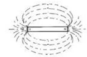
Fig. 2.2 Magnetic field around a magnet
2.3 Magnetic Field
It is the region around the magnet where the forces of attraction or repulsion act on magnetic poles. The magnetic field is strongest near the poles and its strength decreases with increasing distance from the poles.
2.4 Magnetic Flux
In the above experiment, the curved lines formed by the iron filings represent the magnetic lines of force and is known as magnetic flux.
Flux: The word Flux in dictionary means flow through a unit area, here it refers to magnetic lines of forces.
Magnetic flux may be quantified as the total number of magnetic lines of force produced by a magnet or an electromagnet. Magnetic flux is denoted by ϕ and its SI unit is weber (Wb)
1 Wb = 108 magnetic lines of force = 108 Maxwell
If magnetic flux of a bar magnet is 1 Wb, there will be 108 magnetic lines of force joining north and south pole of the bar magnet.
2.4.1 Characteristics of lines of magnetic flux
1. The lines of magnetic flux are imaginary and represent the density and distribution of magnetic field.
2. In non-magnetic medium like air around the magnet, the line of magnetic flux has north to south direction.
3. In magnetic medium like inside a magnet the line of magnetic flux has south to north direction.
4. Thus, lines of magnetic flux form a closed loop (fig. 2.3)
5. The lines of magnetic flux do not intersect each other.
6. Lines of magnetic flux act like stretched cords, always trying to shorten themselves.
7. Parallel lines of magnetic flux which are in the same direction tend to repel each other.
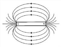
Fig. 2.3 Lines of magnetic flux form a closed loop
2.4.2 Magnetic flux density
The magnetic flux density is the flux per unit area at right angle to the flux at a point.
Flux density, B = ϕ/A
Wb/m2 or Tesla (T) where, ϕ = magnetic flux (Wb), A = area (m2).
2.4.3 Permeability
Permeability is the ability of a material to conduct magnetic flux through it. Permeability is expressed as absolute and relative Permeability and is denoted as µ.
2.4.3.1 Absolute permeability (µ)
It is the actual permeability of a material. Air or vacuum has a poor permeability for magnetic flux and its value is given as:
µo = 4π x 10-7 H/m, where µo = permeability air or vacuum.
2.4.3.2 Relative permeability (µr)
Relative Permeability is the ratio of the absolute permeability of a material (µ) to the absolute permeability of air or vacuum (µo).
µr = absolute permeability of a material / absolute permeability of air or vacuum = µ/ µo
#Relative permeability of air or vacuum = µ/ µo = 1
#Relative permeability of all non magnetic material = 1
Table 2.1 Relative permeability of some materials
|
Material |
Relative permeability |
|
Aluminium |
1.00002 |
|
Air/Vacuum |
1 |
|
Soft iron |
8000 |
|
Steel |
100000 |
|
Nickel |
100.600 |
|
Mu Metal (Nickel, 15% iron + copper + molybdenum) |
50,000
|
|
Metglass Magnetic Alloy 2714A |
10,00,000
|
|
Hydrogen a pure iron- N 5 grade |
1,60,000
|
|
Permeability (nickel iron magnetic alloy) 20% iron & 80% nickel content |
8,000 |
Magnetic material such as soft iron, steel etc have high relative permeability. Therefore it is used for making cores of electromagnet equipments. In Fig. 2.4 ii soft iron core is placed between the two magnets to increase the conductance of magnetic flux. The lines of magnetic flux pass completely through the soft iron ring. It results in a higher flux density in soft iron ring compared to air (Fig. 2.4). Since result in a higher flux density in soft iron is 8000 times the flux density of air.
Direction of magnetic field due to current passing through a horizontal coil and circular coil is shown in Fig. 2.5 and Fig. 2.6 respectively. The magnetic flux in the coil can be classified as useful and leakage flux (Fig. 2.7)
2.5 Electromagnetic Induction
Electromagnetic Induction is a phenomenon by which an e.m.f. can be induced in a conductor by changing the flux linking with the conductor. If the conductor is connected through a closed circuit current will flow in it. The flow of current will take place as long as the flux linking the conductor is changing. Let us consider two cases:
Case 1
The bar magnet is stationary and the flux linking to coil is not changing.
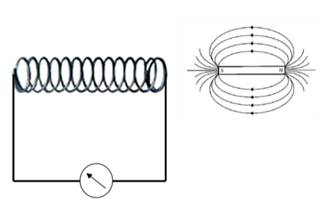
Fig. 2.8 Condition when flux linking the conductor is not changing
Case 2
The bar magnet is moved. The magnet is moved at a rapid pace into & from the coil
· The flux linking to coil changes.
· Magnetic induced emf i.e., voltage generated in coil equal to the rate of change of flux linkages.
(Fig. 2.9 :Condition when flux linking the conductor is changing)
These observations were summed up into two laws known as Faraday’s laws of electromagnetic induction.
First law
E.m.f (voltage) is induced in a coil or conduction when there is a change in magnetic flux linking the conductor.
Second Law
Magnitude of the induction e.m.f is equal to the rate of change of flux linkages.
In a coil of N turns, the flux linking the coil increases from ϕ1 to ϕ2 during the time period the second.
Initial flux linkages = N ϕ1
Final flux linkages = N ϕ2
According to second law, if e is the induced emf in the coil, it is given by the following equation.
e = rate of change of flux linkages
![]()
![]()
![]()
Here (-) ve sign shows that the voltage is induced in a direction such as to oppose the cause that produces it. Direction of magnetic field due to current passing through a conductor (Fig. 2.10) is given by right hand screw rule (Fig. 2.11)
When a conductor is placed between two magnets and current is passed through it (Fig. 2.12), direction of current will determine whether the conductor will be pulled towards magnets (Fig. 2.13) or will be repelled (Fig. 2.13) ii.
Two conductors are placed side by side. Direction of current will determine whether the conductors will be pulled inwards (Fig. 2.14) or will be repelled (Fig. 2.15).
Numerical 1: Consider a coil of 75 turns. A magnet is moved close to the coil in such a way that the rate of change of flux linkages is 15 mWb/s. Calculate the e.m.f induced in the coil.
Given: N = 75
![]()
![]()
Numerical 2: Consider a coil with 500 turns. If the flux linking the coil increase from 0.5 mWb to 1.5mWb in 1 sec, Calculate the induced emf.
Given:
N = 500
ϕ1= 0.5 mWb
ϕ2 = 1.5 mWb
t = 1 sec
![]()
![]()
Numerical 3: Flux of 5 mWb is linked with coil of 600 turns. If the flux is reversed in every 2s, Calculate the e.m.f induced in the coil.
Change in flux dϕ = 5 – (-5) = 10 mWb [Since current is reversed]
Time period dt = 2 s.
Rate
of change of flux = ![]() mWb/s
mWb/s
Emf
induced = e = N ![]() =
= ![]()
Numerical 4: A 6-pole d.c generator consists of 6 fields with coils connected in series. Each coil is of 1500 turns. When the generator is started, there is a magnetic flux of 0.05 Wb/pole. The rotor rotates at such a speed that the value of residual flux becomes 0.005 Wb/pole in 1 sec. Calculate the e.m.f induced in by the generator.
Given:
No. of poles = 6
No. of field windings = 6
No. of turns in each coils = 1500
Total no. of turns = 6×1500 = 9000
Total initial flux = 0.05 × 6 = 0.3 Wb
Total residual or final flux = 0.005 ×6 = 0.03 Wb
Time required for change between initial & final flux = 1 sec.
e.m.f induced
![]()
Numerical 5: A coil having 1000 turns has flux linkage of 10 mWb. If this flux is reversed in 5ms, Calculate the e.m.f induced in the coil.
![]()
N = 1000 turns
dϕ= 10-(-10) = 20 mWb
dt = 5×10⁻³sec.
![]()