Module 1. Alternating and direct current: Fundamentals
Lesson 3
ELECTROMAGNETIC INDUCTION AND MAGNITUDE OF INDUCED E.M.F.-II
3.1 Direction of Induced E.M.F
There are two methods of determining the direction of induced e.m.f.
1. Lenz’s Law
2. Fleming’s Right hand rule
3.1.1 Lenz’s law
Lenz’s law states that the direction of electro-magnetic induced current will be in such a direction so as to oppose the very cause which produces it. By the term “cause” we mean that the change in flux linking the coil is the cause of production of current. Therefore the flow of induced current will be in such a direction that the magnetic field created will oppose the change in the flux which is responsible in producing the induced current.
When N- pole of a bar magnet is brought close to a coil, an e.m.f. is induced in the coil. The direction of the current will be such that ‘B’ side of the coil attains north polarity, So as to oppose the change in the original flux.
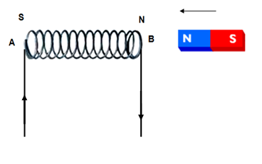
Fig. 3.16 E.m.f. induced in the coil by moving a magnet to and fro
3.1.2 Fleming’s right hand rule
Keep forefinger, middle finger and thumb of your right hand in a position that they are at right angles to each other (Fig. 3.17 (a), and Fig. 3.17 (b)). If the:
a. First finger of the right hand is pointed in the directing magnetic flux.
b. Thumb is pointed in the direction of motion of the conductor.
c. Then the second finger will point in the direction of induced current.

Fig. 3.17 (a) Fleming right hand rule
3.1.3 Fleming’s left hand rule
Fleming's left-hand rule is used for electric motors, while Fleming's right-hand rule is used for electric generators. Separate hands need to be used for motors and generators because of the differences between cause and effect. In an electric motor, the electric current and magnet field exist (which are the causes), and they lead to the force that creates the motion (which is the effect), and so the left hand rule is used. In an electric generator, the motion and magnetic field exist (causes), and they lead to the creation of the electric current (effect), and so the right hand rule is used.(Fig. 3.17 (c))
3.2 Magnitude of Induced E.M.F.
Induced e.m.f. can be classified as:
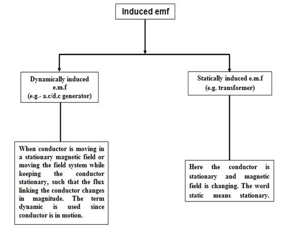
Fig. 3.18 Classification of induced e.m.f.
3.2.1 Dynamically induced e.m.f.
It can occur in two cases:
1. When conductor is moving in stationary magnetic field.
2. Or moving the entire field system while keeping the conductor stationary.
In both the above cases magnetic flux is cut by the conductor to induce e.m.f. in the conductor.
Consider a conductor of length l meters is placed in the magnetic field of magnetic flux density B Wb/m2. The conductor is moving at right angles to the field at velocity v m/s (Fig. 3.19 (a)).
If the conductor moves a small distance dx in dt seconds. Then area swept by the conductor is = l ×dx.
Flux cut by conductor dϕ = Flux density × area swept
= B × l.dx Wb
dϕ = Bldx Wb ......... (Eq. 1)
According to Faraday’s laws of electromagnetic induction, e.m.f (e) induced in the conductor is given by:
![]()
Since N = 1,
![]() ......... (Eq. 2)
......... (Eq. 2)
From
equations 1 & 2.
![]()
![]()
Where,
![]()
If the conductor is moved at an angle θ with the direction of magnetic field at a velocity v m/s, as shown in Fig. 3.19 (b), then:
Area swept by the conductor, A = l × dx Sin θ
Flux cut by conductor dϕ = Flux density × Area swept
dϕ = Bldx Sin θ
![]()
Unsolved numerical
Numerical 1: A wire of length 60 cm is at right angles to a uniform magnetic field having flux density 2 Wb/m2. The velocity of the conductor is 50 m/s. Calculate the induced e.m.f. if conductor moves at an angle 70o to the field. (Ans: 46.43 V)
Numerical 2: A conductor of length 30 cm moves with a velocity of 50 m/s in a uniform magnetic field (flux density 2.5 Wb/m2) Calculate the e.m.f. induced in the conductor when the direction of motion is:
(a) 90o to the magnetic field. (Ans 33.52 V)
(b) Inclined at 30o to the direction of field. (Ans 37.05 V)
3.2.2 Statically induced E.M.F
Here the conductor/ coil and magnetic field system both are stationary.
3.2.2.1 Self induced e.m.f
The e.m.f induced in a coil due to flux change linking with its own turn is known as self induced e.m.f. When current flows through a coil, a magnetic field is established through the coil. If the current flowing in the coil also changes. Due to change in flux linkage an e.m.f will be induced in the coil. According to Lenz’s law the direction of induced e.m.f is such that it opposes the cause which produces it. Thus the direction of this induced e.m.f is toward change of current in the coil.
![]()
When current in the coil is varied, the induced e.m.f. opposes the change of current in the coil. This oppose caused by induced e.m.f delays the change of current in the coil. (Fig. 3.20)
3.2.3 Mutually induced e.m.f
If two coils are placed such that change in current in one coil induces e.m.f in the adjoining coil, it is known a mutually induced e.m.f. Consider two coils A and B is placed side by side as shown in the figure 3.21. When current is passed through coil A links to coil B. The flux common to both the coils (linking A to B) is called mutual flux (ϕm). Varying current in coil A, varies the mutual flux leading to e.m.f induction in both the coils. Now there are two types of induced e.m.f in the two coils A & B.
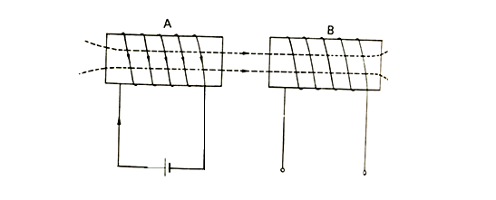
Fig. 3.21 Mutual Inductance
In Coil A: Self-induced e.m.f
Coil B: Mutually induced e.m.f
Characteristics of mutually induced e.m.f.
1. Magnitude of mutually induced e.m.f
![]()
where
Nm = number of turns in coil B.
![]()
2. According to Lenz’s law, the direction of mutually induced e.m.f is as to oppose the very cause producing it. The direction of induced current in coil B due to mutual induced e.m.f will be such that the flux linking coils A & B.
3. The characteristic of two coils such that voltage can be induced in one coil by changing current in the other coil is called mutual inductance.
4. Mutually induced e.m.f in coil B will exists as long as the current in coil A is being changed. If the magnitude of current in coil A comes to a constant value, the mutual flux no longer changes and mutually induced e.m.f (in coil B) drops to zero.
3.3 Coefficient of Self Inductance (L)
Self inductance of the coil may be defined as the property of a coil due to which it opposes the change of current flowing through itself. This property of self inductance is attained by a coil is due to the self induced e.m.f produced in the coil itself by the changing current. The principle of self inductance can be understood taking two cases (Table 3.1):
Table 3.1 Cases for the direction of self induced e.m.f.
|
|
Current in the coil |
Direction of self induced e.m.f. |
|
Case 1 |
Increasing |
Is such to oppose the rise of current ( and opposite to applied voltage) |
|
Case 2 |
Decreasing |
Is such to oppose the decrease of current (and of same direction as the applied voltage) |
Now we should understand that self inductance does not prevent the current from changing, but only causes delay to the change.
3.3.1 Inductance of the coil depends on the following factors:
1. Number of turns in a coil and its shape.
2. Relative permeability (μr) of the material which surrounds the coil.
3. The rate of change of magnetic field. (It can also be said as rate of change of flux linkage).
Self inductance L = Nϕ/I henry.
Where
N = Number of turns in the coil.
ϕ = flux linking with the coil.
I = Current flowing through the coil.
Nϕ= Flux linkages.
3.4 Coefficient of Mutual Inductance
It may be defined as the characteristic of coil due to which it opposes the change of current in the neighbouring coil.
![]()
where,
![]()
ii = current flowing through coil 1.
N1= Number of turns on core of length l meters.
a = area
of cross section.
![]() = relative permeability.
= relative permeability.
N2 = Number of turns in coil 2.
3.5 Coefficient of Coupling
Consider two coils placed adjacent to each other such that flux produced in one coil links to the other. The fraction of magnetic flux produced by the current in one coil linking to other coil is known as co-efficient of coupling (K).
![]()
Where,
L1 & L2 are inductance of coil 1 and 2 respectively.
M = Mutual inductance between them.
Numerical: A coil having 1000 turns has flux linkage of 10 mWb. If this flux is reversed in 5ms, Calculate the e.m.f induced in the coil.
![]()
N = 1000 turns
dϕ= 10-(-10) = 20 mWb
dt = 5×10⁻³sec.
![]()