Module 2. A.C. series and parallel circuits
Lesson 6
A.C. SERIES AND PARALLEL CIRCUITS
6.1 A.C. Circuit
When an alternating current flows in closed loop or a path, it is called an a.c. circuit. Different elements of an a.c. circuit may be any or in combination of following:
1. Resistance: An electrical element which causes opposition to the passage of an electric current through that element.
2. Inductance: In electromagnetism and electronics, inductance in the circuit "induces" (creates) a voltage (electromotive force) in both the circuit itself (self-inductance) and any nearby circuits (mutual inductance). Inductance is typified by the behaviour of a coil of wire in resisting any change of electric current through the coil.
3. Capacitance: Capacitance is the ability of a body to store an electrical charge. Any element or structure that is capable of being charged, either with static electricity or by an electric current exhibits capacitance.
If the voltage applied to an a.c. circuit in sinusoidal, the resulting alternating current is sinusoidal. Also the frequency of the alternating current will be equal to that of applied voltage. The opposition to the flow of current in an a.c. circuit may be due to:
1. Resistance R
2. Inductive reactance (XL = ωL)
3. Capacitive
reactance (XC = ![]() )
)
Different
types of A.C. Circuit can be listed as follows:
1. A.C.
Circuit with only one element
a) Resistance
b) Inductance
c)
Capacitance
2. A.C. Series Circuit
a) R-L
Series Circuit
b) R-C
Series Circuit
c) R-L-C
Series Circuit
3. A.C. Parallel Circuit
6.2 A.C. Circuit with Only One Element
6.2.1
A.C. Circuit with only one element-resistance
The
figure 6.1 shows an a.c. circuit with a pure
resistance of R Ω
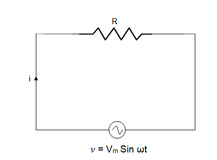
Fig.
6.1 A.C. Circuit with only one element-Resistance
The current in the circuit is i
= v/R .........
(1)
The instantaneous value of alternating voltage is
given by:
v
= VmSin ωt .........
(2)
From equation (1) and
(2)
![]() .........
(3)
.........
(3)
The value of current will be maximum when Sin 𝜔t=1
![]() ......... (4)
......... (4)
From equation (3) and (4)
i
= ImSin ωt ......... (5)
In an a.c. circuit having resistance as any element, the phase
difference between voltage and current is zero. In other words it can be said
that current is in phase with the voltage
power.
We know instantaneous power p = vi
From equation (2) and (5) we have
![]()
![]()
![]()
![]()
Considering average
power
![]()
![]()
![]()
P = Vrms
Irms
p = v i where V = rms voltage, I = rms current
6.2.2
A.C. Circuit with only one element-inductance
Figure 6.2 shows an a.c.
circuit with pure inductance of L Henry
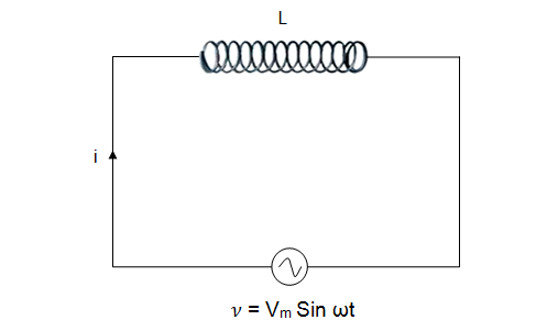
Fig.
6.2 A.C. Circuit with only one element-Inductance
The sinusoidal voltage can be given as
![]()
The e.m.f in the coil due to the current I
flowing in the circuit can be given
as
![]() .........
(2)
.........
(2)
The
induced e.m.f is also called e.m.f
opposes the change of current in the coil .Back e.m.f.
induced in the coil is equal and opposite of the applied voltage. Thus
equation
![]()
Integrating
![]()
![]()
![]() .........
(3)
.........
(3)
i
will be maximum when value of ![]() )
is one
)
is one ![]()
![]() ......... (4)
......... (4)
![]()
In the above equation
ωL is
also known as inductive reactance XL of the coil.
ω =angular
velocity
f =frequency in hertz
L =inductance in henry
XL=inductive reactance in Ω
(ohms)
Note:
XL is the opposition offered by pure inductance to the flow of an
alternating current
From equation (3) and
(4) we have
![]() ......... (5)
......... (5)
From equation (1) and (5) it can be seen that current
in a inductive circuit lags behind the voltage by ![]() radians or 90o.It is well represented
in the phasor diagram shown in fig. 6.3
radians or 90o.It is well represented
in the phasor diagram shown in fig. 6.3

Fig. 6.3 Phasor diagram for
current and voltage in an inductive circuit
Power
Instantaneous power p = v i
![]()
![]()
![]()
Average power consumed over one cycle
![]()
![]()
This shows that power absorbed in a circuit having
only inductance element is zero
6.2.3
A.C. circuit with only one element- capacitance
Fig. 6.4 Shows a circuit with capacitance C farads
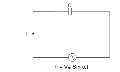
Fig.
6.4 Circuit with capacitance C farads
The value of alternating voltage is given
as
![]()
The charge on the capacitor q=c v
![]()
The current in the circuit is
![]()
![]()
![]()
![]()
![]()
![]() .........
(1)
.........
(1)
The value of the current will be maximum when ![]()
![]()
From equation
(1)
![]()
This equation shows that in a circuit with capacitance
as an only element, the current leads the voltage by 90o (Fig. 6.5)
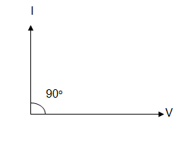
Fig.
6.5 Current leads the voltage by 90o in a circuit with capacitance
Power
Instantaneous power is given by
p = v i
![]()
![]()
![]()
The average power over one complete cycle is p =
Zero
The power absorbed in a circuit with pure capacitance
is zero.
6.3
A.C. Series Circuit
There are three major types of circuit as follows
1.
R-L Series Circuit
2.
R-C Series Circuit
3.
R-L-C Series circuit
6.3.1
R-L series circuit
Figure 6.6 shows a pure resistance and inductance
connected in series
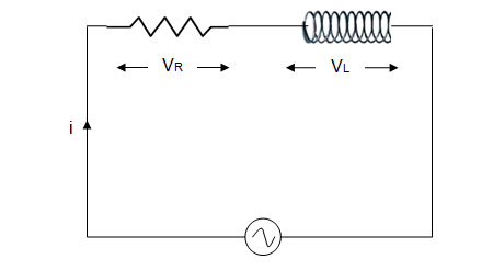
Fig. 6.6
A.C. circuit with series resistance and inductance
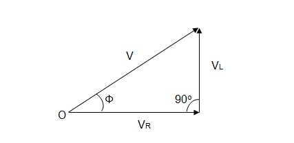
Fig. 6.7 Phasor diagram for a.c. series circuit
From the phasor
diagram
V2 = (VR)2 + (VL)2
![]()
![]()
![]()
![]()
Here,
V = r.m.s value of applied voltage
I = r.m.s. value of current
VR
= voltage drop across R = IR
VL
= voltage drop across L = IXL
Z = Impedance of the circuit and it is measured in Ω
ohms
![]()
![]()
![]()
Here ϕ is
known as phase angle
Voltage leads current by ϕ angle. In other
words it can be said that current lags voltage by ϕ angle.
Figure 6.8 shows the impedance triangle
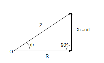
Fig.
6.8 Impedence triangle for a.c.
series circuit
Impedance Z ![]()
![]()
Here,
Z = Impedance and R = Resistance
XL=Inductive reactance
ϕ = Phase angle
Cos ϕ = power factor of the circuit
Power
P= VI Cos ϕ
= (Z.I) ICos ϕ
![]()
P = I2R
In a series R-L Circuit power is consumed in
resistance only. Inductance consumes zero power. The unit of power is
watt.
6.3.2
R-C series circuit
Fig. 6.9 shows a pure resistance and capacitance
connected in series.
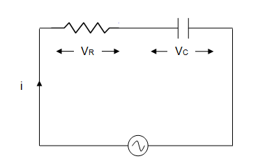
Fig.
6.9 A.C. circuit with series resistance and
capacitance
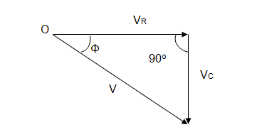
Fig.
6.10 Phasor diagram
for a.c. series resistance and capacitance circuit
From the phasor diagram
figure 6.10
V2 = (VR)2 + (-VC)2
![]()
![]()
![]()
![]()
Here,
V = r.m.s value of applied voltage
I = r.m.s. value of current
VR
= Voltage drop across R = IR
VC
= Voltage drop across C = IXC
Z = Impedance of the circuit and it is measured in
ohms
![]()
![]()
![]()
Here ϕ is known as phase angle.
Current leads voltage by ϕ angle. In other
word can be said that voltage lags current by ϕ angle. The figure
6.11 shows the impedance triangle.
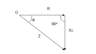
Fig.
6.11 Impedance triangle for a.c. series circuit
Impedance Z![]()
![]()
Here, Z = Impedance and R=Resistance
XC = Capacitive reactance
![]() = Power factor of circuit
= Power factor of circuit
C = Capacitance
XC = ![]() =
Capacitive reactance
=
Capacitive reactance
Power P = VICosϕ![]()
Here,
V = r.m.s value of applied voltage
I = r.m.s. value of current
![]() =
Power factor of circuit
=
Power factor of circuit
6.3.3
R-L-C series circuit
When a pure resistance R ohms, pure inductance L Henry
and pure capacitor of capacitance C farad are connected in series it is known
as R-L-C Series Circuit.
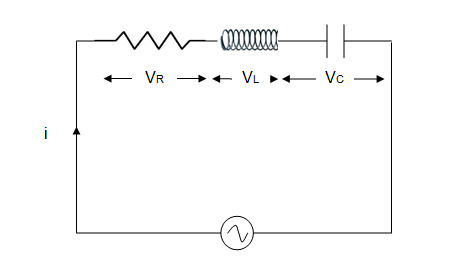
Fig.
6.12 A.C. series circuit for resistance, inductance and capacitance

Fig.
6.13 Phasor diagram for
resistance, inductance and capacitance series circuit
The
voltage drop across each element is given as:
a) Resistance
(R) = VR = IR (in phase with current I)
b) Inductance
(L) = VL = IXL (leads current by 90o)
c) Capacitance
(C) = VC = I.XC( lags current by
90o)
In the phasor diagram VL is leading current I by 90o and VC is lagging current by 90o. So it is evident that
VL and VC are at 180o to each other. In technical terms it is
said to be 180o out
of phase with each other. The circuit will behave like inductive or capacitive
manner depending upon voltage drop VL or VC w.r.t current I.
From the phasor diagram:
![]()
![]()
![]()
![]()
Where
Z = Impedance of the circuit which offers opposition to current flow
Phase Angle
Again from the phasor
diagram
![]()
![]()
![]()
![]()
![]()
Three
cases of R-L-C Series Circuit
The equation for impedance is given as:
![]()
Case 1: When XL>XC
· The term (XL-XC)
is positive.
· The circuit works as an R-L
Series Circuit.
· Current
lags behind voltage.
· Phase
angle is positive.
· Power
angle is positive.
· Power
factor is lagging.
· Current flowing
in circuit i,
![]()
Case 2: When XC>XL
·
The term (XL-XC)
is negative.
·
The circuit works as an R-C
Series Circuit.
·
Current leads over voltage.
·
Phase angle is negative.
·
Power factor is negative.
·
The current flowing in the
circuit i,
![]()
Case 3: When XL = XC
·
The term (XL-XC)
= 0.
·
The circuit works as pure
resistance.
·
Current is in phase with voltage.
·
Phase angle is Zero.
·
Power factor = 1.
·
The current flowing in the
circuit i,
![]()
6.4
True Power and Reactive Power
Table
6.1 Power in the electrical circuit
|
|
|
Formula |
Units |
|
1. True power
|
· Power consumed by watt meter · Is the useful work and the current is in phase with the voltage · Is the power consumed by resistance · It is also known as active power
|
PTrue = V×I Cosϕ
|
Watts
|
|
2. Reactive power
|
· Power consumed in L or C in a circuit is zero but the circulating power is termed as reactive power · Does no useful work and current is 90o out of phase with voltage. · Reactive power cannot be measured by wattmeter. |
PReac = V×I Sinϕ
|
VAR
|
|
3. Apparent power |
· It is defined as the product of Voltage and Current |
Papparent = VI
|
VA |
6.5
Power Triangle
Figure 6.14 shows the power triangle for an A.C.
circuit.
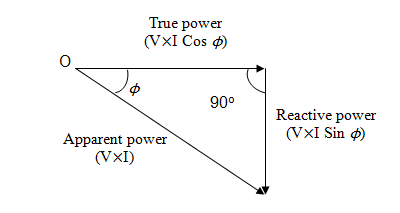
Fig.
6.14 Power triangle for an A.C. circuit
True
power PTrue = V×I Cos ϕ
Reactive
Power PReac = V×I Sin ϕ
Apparent
power Papp = VI
![]()
From
power
triangle
![]()
6.6
A.C. Parallel Circuits
In a.c. circuits R, L and C
are connected in parallel. Voltage across each element is same but the current
flowing through it is different. Equipments, lights and circuits are connected
and operated in parallel. Parallel connection gives advantage that each
equipment, appliance or device can be operated independently having separate
switches for on/off. Parallel circuits are analysed using following methods:
1. Phasor diagram
2. Admittance
method
3. Symbolic
methods
Numerical
1. A coil of R = 100 ohm and L = 125 milli Henry is connected across
alternating voltage e = 250 sin 100𝛑t.
Determine:
a. Impedance
b. Current
through the coil
Solution:
2πft = 100πt
f = 50 Hz
Inductive reactance XL = ![]()
= 2πfL
= 2π50x125x
10-3
= 39.25 ohm
Impedance Z ![]()
Z ![]()
Z = 107. 42 ohm
Current
through coil I = em/Z
= 250/107.42 = 2.32 A
2. A resistance of 50 ohm and capacitor of 200 µF are
connected across 220 V, 50 Hz voltage supply.
Determine:
a. Impedance
b. Current
through the coil
c. Power
factor
Capacitive reactance = XC
= ![]() =
= ![]() =
= ![]() = 15.92 ohm
= 15.92 ohm
Impedance
Z ![]()
Z
![]()
Z
= 52. 47 ohm
Current
I = V/Z = 220/52.47 = 4.19 A
Power
factor Cos ϕ = R/Z = 50/52.47 = 0.953
leading
3. A resistance of 50 ohm, inductance 75 mH and capacitor of 25 µF are connected across 220 V, 50 Hz voltage supply. Determine:
a. Impedance
b. Current
through the coil
c. Power
factor
Inductive
reactance XL = ![]()
= 2πfL
= 2πx50x75x 10-3
= 23.55 ohm
Capacitive reactance = XC = ![]() =
=
![]() =
= ![]() = 127.38 ohm
= 127.38 ohm
Impedance Z ![]()
Z ![]()
Z = 115.24 ohm
Current
I = V/Z = 220/115.24 = 1.9 A
Power
factor Cos ϕ = R/Z = 50/115.24 = 0.433
leading