Module 3. Transformers
Lesson 10
TRANSFORMER THEORY-I
10.1 Introduction
Transformer is used to increase or decrease the voltage. Transformer is an important electrical machine in a power system (Fig. 10.1). A transformer is a device that transfers electrical energy from one circuit to another through inductively coupled conductors—the transformer's coils. A varying current in the first or primary winding creates a varying magnetic flux in the transformer's core and thus a varying magnetic field through the secondary winding. This varying magnetic field induces a varying electromotive force (EMF), or "voltage", in the secondary winding. This effect is called inductive coupling.
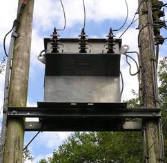
Fig. 10.1 A pole mount transformer
Electrical power is generated at power plant (Thermal/Hydel/Nuclear) generally at 11 kV. The voltage is stepped up to 220 kV or 400 kV for transmission to long distances. It is done to reduce loss and increase distribution efficiency. Transformer can be broadly classified as:
10.1.1 Step up transformer
When output voltage is greater than input voltage (V2>V1).
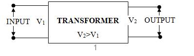
Fig. 10.2 Step up transformer
10.1.2 Step down transformer
When output voltage is less than input voltage (V2<V1).
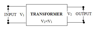
Fig. 10.3 Step down transformer
10.2 Principle of Operation
Transformer works on the principle of electromagnetic induction. The basic elements of a transformer are (Fig. 10.3):
1. Steel core: on which primary and secondary winding are done.
2. Primary winding: a.c. supply is connected.
3. Secondary winding: Load is connected.
When primary winding is connected to a.c. voltage V1, an alternating flux is set up in the core. This alternating flux links with the secondary winding through the steel core. An e.m.f. is induced in the secondary winding known as mutually induced e.m.f. According to Lenz’s law the direction of induced e.m.f. V2 is opposite to the applied voltage V1 (Fig.10.4).
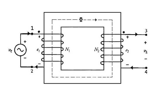
Fig. 10.4 Direction of induced emf in secondary coil is opposite to applied voltage
The primary and secondary windings are not connected but due to mutual flux emf is induced in the secondary coils.
10.3 E.m.f. Equation of a Transformer
Consider a transformer having
N1 number of turns in primary side
N2 number of turns in secondary side
The transfer is updated by a.c input of frequency f. Let Φm be the maximum flux in the transfer core.
Φm = Bm × A
Where
Φm = Maximum flux in core , Wb
Bm= Maximum flux density
A = area of core
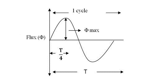
Fig. 10.5 Wave form of alternating flux
From above figure it is evident that flux increase from zero to the maximum value Φm in T/4 seconds.
![]()
![]()
![]() ......... (1)
[Since T = 1/f]
......... (1)
[Since T = 1/f]
We know,
Form factor = r.m.s. value/average value = 1.11
Or, r.m.s value = 1.11 × average value ......... (2)
From eqn (1) & (2)
r.m.s value of e.m.f/ turn = 1.11 × 4 f Φm volts
= 4.44 f Φm volts/turn
r.m.s value of induced emf in primary winding having N1 turns
E1 =4.44 f Φm N1 volts ......... (3)
r.m.s value of induced emf in secondary winding having N2 turns
E2 = 4.44 f Φm N2 volts ......... (4)
Dividing equation (4) & (5)
![]()
Or
![]() .........
(5)
.........
(5)
The ratio of secondary voltage (E2) to primary voltage (E1) is known as transformation ratio (K).
· Step up transformer N2 > N1 or K > 1
· Step down transformer N1 > N2 or K < 1
In case of an ideal transformer
Input power = output power
![]()
or
![]()
![]() .........
(6)
.........
(6)
From (5) & (6)
![]()
10.3.1 Turn ratio
The ratio of secondary to primary turns is called turn ratio,
turn ratio= N2/N1.
If N2>N1 transformer is step-up transformer
If N2<N1 transformer is step-down transformer.
The relationship between transformation ratio and turn ratio is given as:
![]()
10.4 Working
When an alternating voltage V1 is applied
to the primary, an alternating flux ![]() is
set up in the core. The alternating flux links both the windings and induces e.m.f.s E1 and E2 in them according
to Faraday’s laws of electromagnetic induction. The e.m.f.
E1 is termed as primary e.m.f. and e.m.f. E2 is termed as secondary e.m.f.
is
set up in the core. The alternating flux links both the windings and induces e.m.f.s E1 and E2 in them according
to Faraday’s laws of electromagnetic induction. The e.m.f.
E1 is termed as primary e.m.f. and e.m.f. E2 is termed as secondary e.m.f.
![]()
![]()
![]()
Note that
magnitude of E2 and E1 depend upon the number of turns on
the secondary and primary respectively. If N2>N1, then
E2>E1 (or V2>V1) and we get a
step-up transformer. On the other hand, if N2<N1, then
E2<E1 (or V2<V1) and we get a
step-down transformer. If load is connected across the secondary winding, the
secondary e.m.f. E2 will cause a current I2
to flow through the load. Thus, a transformer enables us to transfer a.c. power from one circuit to another with a change in
voltage level. The following points may be noted carefully:
· The transformer action is based
on the laws of electromagnetic induction.
· There is no electrical connection
between the primary and secondary. The a.c. power is
transferred from primary to secondary through magnetic flux.
· The transformer cannot work on d.c. power.
· There
is no change in frequency i.e. output power has the same frequency as the input
power.
·
The losses that occur in a
transformer are:
a)
Core losses-eddy current and hysteresis.
b)
Copper losses-in the resistance of the windings.
In
practice, these losses are very small so that output power is nearly equal to
the input primary power. In other words, a transformer has very high
efficiency.
10.5
Application of Transformer
10.5.1
Power distribution
Big
generating stations are located at hundreds or more km away from the load center (where the power will be actually consumed). Long
transmission lines carry the power to the load centre from the generating
stations. Generator is a rotating machines and the level of voltage at which it
generates power is limited to several kilo volts only a typical value is 11 kV.
To transmit large amount of power (several thousands of mega watts) at this
voltage level means large amount of current has to flow through the
transmission lines. The cross sectional area of the conductor of the lines
accordingly should be large. Hence cost involved in transmitting a given amount
of power raises many folds. Not only has that, the transmission lines had their
own resistances. This huge amount of current will cause tremendous amount of
power loss or I2R loss in the lines. This loss will simply heat the
lines and becomes a wasteful energy. In other words, efficiency of transmission
becomes poor and cost involved is high. The above problems may address if we
could transmit power at a very high voltage say, at 200 kV or 400 kV or even
higher at 800 kV. But as pointed out earlier, a generator is incapable of
generating voltage at these levels due to its own practical limitation. The
solution to this problem is to use an appropriate step-up transformer at the
generating station to bring the transmission voltage level at the desired value
as depicted in figure 10.6 where for simplicity single phase system is shown to
understand the basic idea.
Fig. 10.6 Power transmission system
Obviously
when power reaches the load centre, one has to step down the voltage to
suitable and safe values by using transformers. Thus transformers are an
integral part in any modern power system. Transformers are located in places
called substations. In cities or towns you must have noticed transformers are
installed on poles – these are called pole mounted distribution transformers.
These type of transformers change voltage level typically from 3-phase, 6 kV to
3-phase 440 V line and then to 220 V line.
10.5.2
Domestic use
Small transformers are used in the mobile charger, emergency light etc to bring 220 V domestic supply
to low voltage may be 4.5 V or 6 V.
10.6
Construction of Transformer
1. Steel
core: Silicon steel in the form of thin laminations is used
for the core material. The core is laminated to minimize the eddy current loss.
These laminations are coated with a thin layer of insulating varnish, oxide or
phosphate. The thickness of laminations ranges from 0.35 mm to 0.5 mm. The
construction can be core type or shell type:
a)
Core type: In a core type construction the winding surrounds the
core. The laminations are cut in L shape and are assembled in form of
rectangular frame (Fig. 10.7). To prevent flux leakage primary and secondary
windings are placed overlapping on the limbs of core.
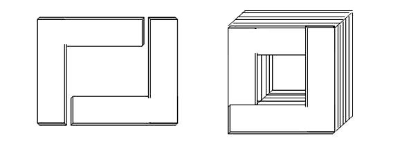
Fig. 10.7 Core type transformer
b)
Shell type: In case of shell-type transformer, individual
laminations are cut in the form of long strips of E’s and I’s
as shown in fig 10.8. In order to avoid high reluctance at the joints where the
laminations are butted against each other, the alternate layers are stacked
differently to eliminate continuous joints.
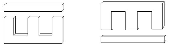
Fig. 10.8 Shell type transformer
In a
shell-type transformer, the core has three limbs, the central limb carries
whole of the flux, where as the side limbs carry half of the flux. Therefore, the width of the central limb as about double to that of
the other limbs. Both of the primary and secondary windings are
placed on the central limb side by side or concentrically. The low voltage
winding is placed nearer the core and the high voltage winding is placed
outside the low voltage winding to reduce the cost of insulation placed between
core and low voltage winding. In this case also the windings are form-wound in
cylindrical shape and the core laminations are inserted later on.
2. Windings:
Windings form another important part of transformers. In
a two winding transformer two windings would be present. The one which is
connected to a voltage source and creates the flux is called primary winding.
The second winding where the voltage is induced by induction is called a
secondary. If the secondary voltage is less than that of the
primary the transformer is called a step down transformer. If the
secondary voltage is more then it is a step up transformer. A step down
transformer can be made a step up transformer by making the low voltage winding
as its primary. Hence it may be more appropriate to designate the windings as
High Voltage (HV) and Low Voltage (LV) windings. The winding with more number
of turns will be a HV winding. The current on the HV side will be lower as V-I
product is a constant and given as the VA rating of the machines. Also the HV
winding needs to be insulated more to withstand the higher voltage across it.
HV also needs more clearance to the core, yoke or the body. These aspects
influence the type of the winding used for the HV or LV windings.
a. Primary winding: a.c. supply is connected.
b. Secondary winding: Load is connected.
3. Container/tank:
It forms the outer covering and body of the
transformer. It is filled with oil in case of oil cooled transformers.
4. Bushings:
Are required for connecting the ends of the winding to
the external circuit. Bushings are made of porcelain and it insulate
the terminals from the transformer body. Two separate bushings are provided for
High Voltage (HV) and Low Voltage (LV) connections (Fig. 10.9).
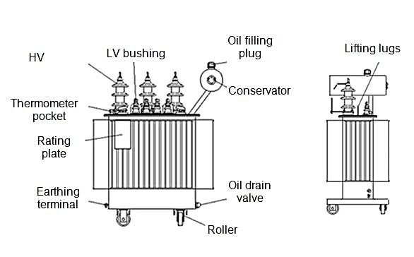
Fig. 10.9 Outer construction of a transformer
5. Cooling
arrangement: Heat is produced in a transformer by the iron losses
in the core and I2R loss in the windings. To prevent undue
temperature rise, this heat is removed by cooling. Type of
cooling methods used are:
·
Dry type transformer: Natural air circulation, air
blast
·
Liquid (oil) immersed: self-cooled, forced air cooled,
forced water cooled, forced oil cooled
a)
In small transformers (below 50 kVA),
natural air cooling is employed i.e. the heat produced is carried away by the
surrounding air.
b)
Medium size power or distribution transformers are
generally cooled by housing them in tanks filled with oil. The oil serves a
double purpose, carrying the heat from the windings to the surface of the tank
and insulating the primary from the secondary. Self oil cooled transformer have
cooling tubes on the outer body. Due to heat dissipation from the winding
convective circulation of oil occurs in the cooling tubes.
c)
For large transformers, external radiators are added
to increase the cooling surface of the oil filled tank. The oil circulates
around the transformer and moves through the radiators where the heat is
released to surrounding air. Sometimes cooling fans blow air over the radiators
to accelerate the cooling process (Fig. 10.10).
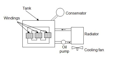
Fig. 10.10 Oil cooled
transformer
Numericals
1. Calculate
transformation ratio if the voltage in the primary and secondary coil are 11000
and 440 volts respectively.
transformation ratio ![]()
= ![]()
2.
Calculate the number of turns in the secondary coils of a transformer if
transformation ratio is 10 and number of turns in primary side is 2500.
Given
K = 10
N1
= 2500
K = N1
/ N2
N2
= 10 × 2500
= 25000 turns.
3.
If the number of turns in the primary and secondary windings of the transformer
is 500 and 1000 respectively. Find the voltage in the secondary side of
transformer. The primary side voltage is 220 V.
transformation
ratio K = N1 / N2 = 500/1000 =0.5
![]()
![]()
E2 = 110 V