Module 4. Alternators
Lesson 16
E.M.F. IN ALTERNATORS, CIRCUIT BREAKERS
16.1 E.M.F in Alternators
In an alternator, let,
No. of poles=P
Rotor speed in rpm=N
Frequency of the induced e.m.f=f
Number of turns in the coils=T
Flux per poles = ∅ Wb
In one rotation of the rotor the flux cut by the conductor = ∅ p Webers ……… (1)
Number of rotation in a min=N
![]()
![]() ……… (2)
……… (2)
![]()
![]()
![]() ……… (3)
……… (3)
Total number of conductor or coil sides per phase=2T
Then average e.m.f
![]() ……… (4)
……… (4)
![]()
![]() ……… (5)
……… (5)
From equation 4 and 5
![]()
![]()
![]() ……… (6)
……… (6)
![]() ………
(7)
………
(7)
From equation 6 and 7
![]()
16.2 Circuit Breakers
Before moving into the topic of circuit breakers we need to first know the hazards available with electric current. Electricity has become a necessity for life. But with all the usefulness, electric power has certain dangers. An electric shock can cause hazards to man. The effect of an electric shock depends on the magnitude of current passing through the human body and duration of contact. Electric shock can sometimes be dangerous to life. The consequences of electric shock are listed below (Table 16.1):
Table 16.1 Consequences of electric shock
|
|
Electric current intensity (A) |
Consequence to human body |
|
1. |
0.001-0.0075 |
Slight sensation |
|
2. |
0.0075-0.01 |
Mild sensation |
|
3. |
0.01-0.075 |
Painful sensation |
|
4. |
0.075-1 |
-Difficulty in breathing -Ventricular fibrillation -Paralyzing respiratory system -Severe burns |
The effect of electric shocks on human body depends, mainly on faulty current and the time of its action. Maximum permissible contact voltages with respect to time of disconnection are as follows:
Table 16.2 Maximum permissible contact voltages with respect to time of disconnection
|
Maximum Permissible Contact Voltage in V |
Disconnection time in (S) |
|
240 |
0.04 |
|
220 |
0.05 |
|
110 |
0.2 |
|
75 |
1 |
|
50 |
5 |
|
<50 |
|
A circuit breaker is an automatic electric switch which protects an electrical circuit from damage caused by overload or short circuit. It stops the flow of current as soon as it detects a fault condition. In a fuse the wire is to be placed in the fuse clamp. But in a circuit breaker there is no fuse. It can be reset manually or automatically to resume normal conditions.
16.3 Ground Fault Circuit Interrupter (GFCI)
GFCI is a special safety circuit used primarily with outdoor circuits and in places where the risk of death by electric shock is greatest. A GFCI provides protection from potentially lethal ground loops by sensing both the hot wire (B) and the neutral (N) currents. If the difference between hot wire current IB and the neutral current IN is more than a few milli amperes then the GFCI disconnects the circuit nearly instantaneously.
Any significant difference between the hot and neutral (return path) currents means that a second path to ground has been created and a potentially dangerous condition has arisen. GFCI are typically reset table circuit breakers so that one does not need to replace a fuse every time.
16.4 Miniature Circuit Breaker (MCB)
Once a fault is detected, contacts within the circuit breaker must open to interrupt the circuit; some mechanically-stored energy (using something such as springs or compressed air) contained within the breaker is used to separate the contacts, although some of the energy required may be obtained from the fault current itself. Small circuit breakers may be manually operated; larger units have solenoids to trip the mechanism, and electric motors to restore energy to the springs.
The circuit breaker contacts must carry the load current without excessive heating, and must also withstand the heat of the arc produced when interrupting the circuit. Contacts are made of copper or copper alloys, silver alloys, and other materials. Service life of the contacts is limited by the erosion due to interrupting the arc. Miniature and molded case circuit breakers are usually discarded when the contacts are worn, but power circuit breakers and high-voltage circuit breakers have replaceable contacts.
16.4.1 Construction
The 10 ampere DIN rail-mounted thermal-magnetic miniature circuit breaker is the most common style in modern domestic consumer units and commercial electrical distribution boards throughout Europe. The design includes the following components:
1. Actuator lever - used to manually trip and reset the circuit breaker. Also indicates the status of the circuit breaker (On or Off/tripped). Most breakers are designed so they can still trip even if the lever is held or locked in the "on" position. This is sometimes referred to as "free trip" or "positive trip" operation.
2. Actuator mechanism - forces the contacts together or apart.
3. Contacts - Allow current when touching and break the current when moved apart.
4. Terminals
5. Bimetallic strip.
6. Calibration screw - allows the manufacturer to precisely adjust the trip current of the device after assembly.
7. Solenoid
8. Arc divider/extinguisher
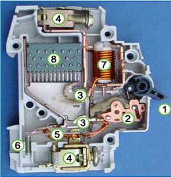
Source: Wikipedia.com
Fig. 16.1 Circuit breaker
16.4.2 Application
16.4.2.1 MCB (Miniature Circuit Breaker)
Rated current not more than 100 A. Trip characteristics normally not adjustable. Thermal or thermal-magnetic operation.
16.4.2.2 MCCB (Molded Case Circuit Breaker)
Rated current up to 2500 A. Thermal or thermal-magnetic operation. Trip current may be adjustable in larger ratings.
Numerical
1. Calculate average emf generated by an alternator if flux per pole is 0.025 Wb, frequency of the current is 40 Hz, number of turns in the coil is 100.
![]()
![]()
2. Calculate the rms value if voltage generated in the above numerical
![]()
![]()