Module 5. Induction motors
Lesson 17
CONSTRUCTION OF INDUCTION MOTORS
17.1 Introduction
Induction motors work on the principle of electromagnetic induction. Electrical energy from the stator winding is transferred to the rotor winding by electromagnetic induction. Therefore these are called as induction motors.
17.2 Types of Induction Motors
17.2.1 Single phase induction motors
It is used for domestic electrical appliances like washing machines, juicer/mixers, refrigerators etc. These machines are built in small sizes upto 3 hp.
17.2.2 3-Phase induction motor
About 90% of mechanical power in the industry is provided by 3-phase induction motors. e.g. conveyors, elevators, large capacity pumps etc.
17.2 Constructional Features of a Three Phase Induction Motor
A 3-phase induction motor (Fig. 17.1) consists of two main parts namely stator and rotor (Fig. 17.2).

Fig.17.1 Three phase induction motor

Fig. 17.2 Stator and rotor of three phase induction motor
17.3.1 Stator
It is the outer body of the motor and consists of outer frame, stator core and windings.
17.3.1.1 Outer frame
The outer frame acts as housing for the motor and supports the stator core. It also protects the inner parts of the motor. Fins are provided on the outer surface of the frame for heat dissipation and cooling of the motor. Frame is provided with legs/base plate to bolt it on the foundation. Motor housing is the outer cover or frame of the motor which contains stator, rotor and other parts. Fins are provided on the outer frame to increase heat dissipation. Housing can be square (Fig. 17.3) or round (Fig. 17.4).
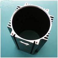
Fig. 17.3 Square motor housing
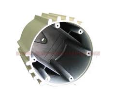
Fig. 17.4 Round motor housing
Depending on the application it can made of any one of the following material:
a. Aluminum/ Aluminum alloy (Fig. 17.5)
b. Mild Steel (Fig. 17.6)
c. Stainless Steel (Fig. 17.7)
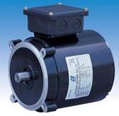
Fig. 17.5 Aluminum motor housing
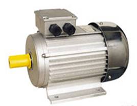
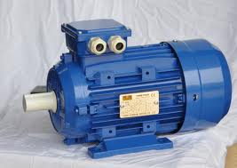
Fig. 17.6 Mild steel motor housing
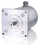
Fig. 17.7 Stainless steel motor housing
17.3.1.2 Stator core
It is made of high grade silicon steel stampings of thickness 0.3 to 0.6 mm which are insulated from each other by a varnish layer. To minimize the hysteresis and eddy current losses core is constructed of steel stampings of high magnetic permeability. The stampings are assembled one over the other under hydraulic pressure and are fixed into the frame. The function of stator core is to carry the alternating magnetic field. Slots are cut on the inner side of the stamping, as shown in fig. 17.9, to accommodate stator winding.
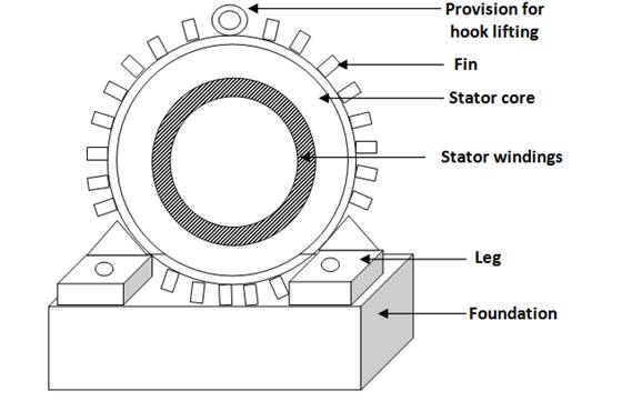
Fig. 17.8 Outer frame
Fig. 17.9 Stator Stamping
17.3.1.3 Stator winding
Coils of insulated wires are inserted into the slots of the stator. Each grouping of coils, together with the core it surrounds, forms an electromagnet (a pair of poles) on the application of AC supply. The number of poles of an AC induction motor depends on the internal connection of the stator windings. The three phase stator windings are connected directly to the three phase power source. Internally they are connected in such a way, that on applying AC supply, a rotating magnetic field is created. There are six terminals of the stator winding; two for each phase are connected in the terminal box of the motor. Number of poles depends on the speed requirement. For lower speed more number of poles are required as,
![]()
![]()
17.3.1.4 Rotor
It is the rotating part of the motor. There are two types of rotor, which are employed in 3-phase induction motors.
(i) Squirrel cage rotor
(ii) Phase wound rotor or slip ring rotor
a) Squirrel cage rotor
The term squirrel cage comes from the shape of the rotor which resembles the shape of the cage of squirrel animal (Fig. 17.10). Almost 90% of induction motors have squirrel cage rotors. This is because the squirrel cage rotor has a simple and rugged construction. The rotor consists of a cylindrical laminated core with axially placed parallel slots for carrying the conductors. Each slot carries a copper, aluminum, or alloy bar. These rotor bars are permanently short-circuited at both ends by means of the end rings (Fig. 17.11). As the rotor bar ends are permanently short circuited, it is not possible to add any external resistance in the rotor circuit.
The slots and bars of the rotor are generally not constructed parallel to the shaft (Fig. 17.11) but are skewed (Fig. 17.12). Here skewed means that the bars and slots are constructed at an angle (Fig. 17.13). Circuit diagram of squirrel cage induction motor is shown in fig. 17.14.
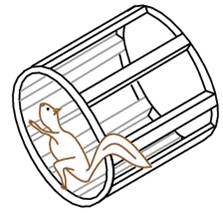
Fig. 17.10 Rotor resembles the cage of squirrel animal
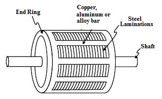
Fig. 17.11 Rotor assembly with parallel bars
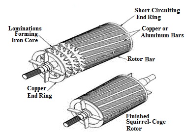
Fig. 17.12 Rotor assembly with skewed bars
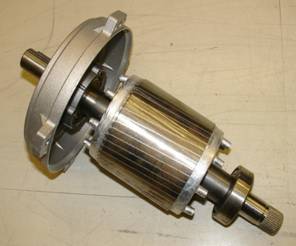
Fig. 17.13 Bars and slots of rotor assembly (Skewed)
Skewing of rotor has the following advantages:
(a) It results in a smoother torque curves for different positions of the rotor,
(b) Quiet running of a motor by reducing magnetic humming.
(c) Helps to reduce magnetic locking of the stator and rotor. The rotor teeth tend to remain locked under the stator teeth due to direct magnetic attraction between the two. This happens when the number of stator teeth is equal to the number of rotor teeth.
(d) It increases the rotor resistance due to increased length of the rotor bar conductors.
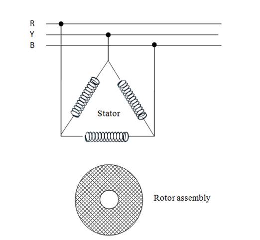
Fig. 17.14 Electrical circuit diagram of squirrel cage induction motor
b) Phase wound rotor or slip ring rotor
An alternate design, called the wound rotor, is used when variable speed is required. The rotor consists of a laminated cylindrical core having slots at the outer periphery and carries a 3-phase insulated winding. In this case, the rotor has the same number of poles as the stator and the windings are made of wire, connected to slip rings on the shaft (Fig. 17.15). Carbon brushes connect the slip rings to an external controller such as a variable resistor that allows changing the motor's slip rate. Depending upon the requirement any external resistance can be added in the rotor circuit. The motors using this type of rotor are known as phase wound or slip ring induction motors. Electrical circuit diagram of slip ring induction motor is shown in Fig. 17.16.
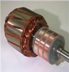
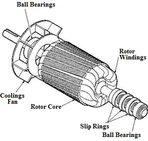
Fig 17.15 Phase wound or slip ring rotor

Fig 17.16 Electrical circuit diagram of slip ring induction motor
Numerical
1. Calculate synchronous speed of the motor if frequency is 50 Hz and number of poles is 8.
Solution
![]()
![]()
2. At 50 Hz the motor rotates at 500 rpm. Calculate the frequency of the supply current to obtain motor speed of 1000 rpm.
Solution
![]()
![]()
Equating two equations
![]()
![]()
![]()
![]()