Module 5. Induction motors
Lesson 18
PRINCIPLE OF INDUCTION MOTORS
18.1 Induction Motors
Induction motors work on the principle of electromagnetic induction. Electrical energy from the stator winding is transferred to the rotor winding by electromagnetic induction. Therefore these are called as induction motors.
Induction motors are widely used for industrial purpose because these motors are probably the simplest, low cost, high efficiency, low maintenance and most rugged of all electric motors. Two basic parts of induction motors are the wound stator and the rotor assembly. The rotor consists of laminated, cylindrical iron cores with slots to accommodate the conductors/windings. Fig 18.1 shows a induction motor. Types and detailed construction of induction motor will be taken up in the next lesson.
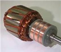
Fig. 18.1 Construction of the rotor
18.2 Production of Rotating Field
Consider a 3-phase induction motor having three windings placed 120o electrically apart. When 3-phase supply is given to the 3-phase winding, a rotating magnetic field of constant magnitude is set up by the stator. The speed of rotating field is that of the magnetic flux developed in the stator winding. The stationary rotor is effected by this magnetic field and emf is induced in the rotor windings. The conductors/windings of the rotor are short circuited at its end and therefore current is set up in the windings. Flow of current in the windings will set up a magnetic field in the rotor. Rotor windings will experience a thrust force according to Flemming right hand rule and rotor assembly starts rotating in the same direction in which the stator field is rotating. To reverse the direction of rotation of rotating field the connections of any two supply terminals are inter-changed.
The three-phase induction motor operates on the principle of a rotating magnetic field. The following discussion shows how the stator windings can be connected to a three-phase ac input and have a resultant magnetic field that rotates. Fig. 18.2 a-c shows individual windings for each phase . Figure 18.2 d shows how the three phases are tied together in a Y-connected stator. The dot in each diagram indicates the common point of the Y-connection. You can see that the individual phase windings are equally spaced around the stator. This places the windings 120º apart.
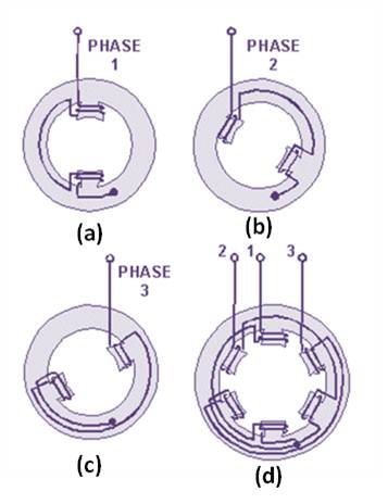
Fig. 18.2 Three phase stator
The three-phase input voltage to the stator of figure 18.2 is shown in the graph of figure 18.3. Use the left-hand rule for determining the electromagnetic polarity of the poles at any given instant. In applying the rule to the coils in figure 18.2, consider that current flows toward the terminal numbers for positive voltages, and away from the terminal numbers for negative voltages.
The results of this analysis are shown for voltage points 1 through 7 in figure 18.3. At point 1, the magnetic field in coils 1-1A is maximum with polarities as shown. At the same time, negative voltages are being felt in the 2-2A and 3-3A windings. These create weaker magnetic fields, which tend to aid the 1-1A field. At point 2, maximum negative voltage is being felt in the 3-3A windings. This creates a strong magnetic field which, in turn, is aided by the weaker fields in 1-1A and 2-2A. As each point on the voltage graph is analyzed, it can be seen that the resultant magnetic field is rotating in a clockwise direction. When the three-phase voltage completes one full cycle (point 7), the magnetic field has rotated through 360º .

Fig. 18.3 Three phase rotating field
18.3 Slip
The speed at which the magnetic field rotates is the synchronous speed of the motor and is determined by the number of poles in the stator and the frequency of the power supply.
![]()
Where:
Ns = synchronous speed
f = frequency
P = number of poles
Synchronous speed is the absolute upper limit of motor speed. At synchronous speed, there is no difference between rotor speeds and rotating field speed, so no voltage is induced in the rotor bars, hence no torque is developed. Therefore, when running, the rotor must rotate slower than the magnetic field. The rotor speed is just slow enough to cause the proper amount of rotor current to flow, so that the resulting torque is sufficient to overcome winding and friction losses, and drive the load. This difference between the rotor speeds (N) and rotating magnetic field speed (Ns), called slip, is normally referred to as a percentage of synchronous speed:
![]()
![]()
Where,
%S= Percent slip
S= Fractional slip
Ns = synchronous speed
N = actual rotor speed
Rotor speed, N = Ns (1−S)
The difference between synchronous speed and rotor speed is called slip speed:
Slip speed = Ns−N
The difference between the rotor speed and synchronous speed of flux determine the rate at which the flux is cut by the rotor conductors and hence the magnitude of induced e.m.f. e2 ∝ Ns−N
Since,
Rotor current, i2 ∝ e2
and torque, T ∝ i2
T∝ (Ns-N)
or T= K (Ns-N)
or ![]()
or T = K’ S
or T ∝ S
Thus, greater the slip greater will be the induced e.m.f. and thus motor will develop higher torque. At no-load conditions, induction motor requires small torque to meet with the mechanical, iron and other losses, therefore, slip is small. When the motor is loaded, greater torque is required to drive the load, therefore, the slip increases and rotor speed decreases slightly. Slip in an induction motor adjusts itself to such a value so as to meet the required moving torque under normal operation. The value of slip varies from about 6% for small motors and 2% for large motors.
18.4 Frequency of Rotor Current
The frequency of rotor currents depends upon the relative speed between rotor and stator field. When the rotor is stationary, the frequency of rotor currents is the same as that of the supply frequency but when the rotor starts rotating, the frequency of rotor current will depend on the slip speed (Ns−N).
If (Ns-N) is slip, P no. of poles then the frequency of rotor current fr is given as
![]()
![]()
![]()