Module 6. D.C. machines
Lesson 23
TYPES AND CHARACTERISTICS OF D.C. GENERATORS
23.1 Types of D.C. Generators
D.C. generators can be classified as:
1. Permanent magnet type
2. Electromagnet type
23.2 Permanent Magnet Type
In this type of generator the poles are made of permanent magnet. The poles do not require any windings. Such type of D.C. generators are of small size. These are employed mainly in dynamo in cycles and bikes. It is not used for industrial purpose because:
a. It would require large magnet which is economically not feasible.
b. Magnetic strength decreases with time so magnetic flux will not remain constant.
23.3 Electromagnet Type
The poles of D.C. generator is magnetized using windings. Electromagnetic type generators can further classifies as:
(i) Externally exited D.C. generator,
(ii) Self-exited D.C. generator.
23.3.1 External or separately excited D.C. generators
A D.C. generator whose field magnet winding is supplied from an independent external D.C. source (e.g., a battery etc.) is called a separately excited generator. Fig. (23.1) shows the connections of a separately excited generator. The voltage output depends upon the speed of rotation of armature and the field current (Eg =PΦ ZN/60 A). The greater the speed and field current, greater is the generated e.m.f. It may be noted that separately excited D.C. generators are rarely used in practice. The D.C. generators are normally of self-excited type
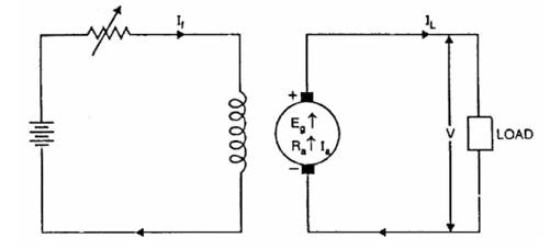
Fig. 23.1 External or separately excited D.C. generators
Armature current, Ia = IL
Terminal
Voltage, V = Eg – IaRa
Electric power developed = EgIa
Power
delivered to load =![]()
23.3.2 Self-excited D.C. generators
A D.C. generator whose field magnet winding is supplied with current from the output of the generator itself is called a self-excited generator. There are three types of self-excited generators depending upon the manner in which the field winding is connected to the armature, namely;
(i) Series generator
(ii) Shunt generator
(iii) Compound generator
23.3.2.1 Series generator
In a series wound generator, the field winding is connected in series with armature winding so that whole armature current flows through the field winding as well as the load. (Fig. 23.2) shows the connections of a series wound generator. Since the field winding carries the whole of load current, it has a few turns of thick wire having low resistance. Series generators are rarely used except for special purposes e.g., boosters.
Armature current, Ia = Ise = IL = I(say)
Terminal voltage, V = Eg – I (Ra + Rse)
Power developed in armature = EgIa
Power delivered to load
= ![]()
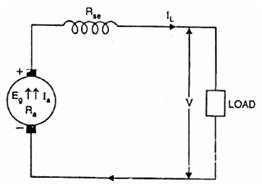
Fig. 23.2 Series generator
23.3.2.2 Shunt generator
In a shunt generator, the field winding is connected in parallel with the armature winding so that terminal voltage of the generator is applied across it. The shunt field winding has many turns of fine wire having high resistance. Therefore, only a part of armature current flows through shunt field winding and the rest flows through the load. (Fig. 23.3) shows the connections of a shunt-wound generator.
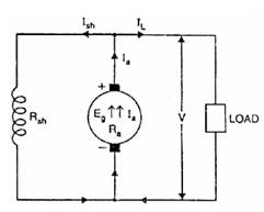
Fig. 23.3 Shunt generator
Shunt field
current, Ish = V/Rsh
Armature
current, Ia = IL
+ Ish
Terminal
voltage, V = Eg – IaRa
Power developed
in armature = EgIa
Power delivered
to load = VIL
23.3.2.3 Compound generator
In a compound-wound generator, there are two sets of field windings on
each pole—one is in series and the other in parallel with the armature. A
compound wound generator may be:
(a) Short Shunt in which only shunt field winding is in parallel with the armature winding (Fig. 23.4).
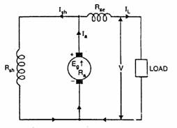
Fig. 23.4 Short shunt generator
(b) Long Shunt in which shunt field winding is in parallel with both series field and armature winding (Fig. 23.5).
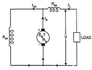
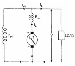
Fig. 23.5 Long shunt generator
Short shunt
Series field current, Ise = IL
Shunt field
current, ![]()
Terminal Voltage, V = Eg – IaRa – IseRse
Power developed in armature = EgIa
Power delivered to load = VIL
Long shunt
Series field current, Ise = Ia = IL + Ish
Shunt field current, Ish = V/Rsh
Terminal voltage, V = Eg – Ia (Ra + Rse)
Power developed in armature = EgIa
Power delivered to load = VIL
23.4 Efficiency of d.c. generators
Various power stages in the case of a d.c generator are shown in Fig. 23.6.
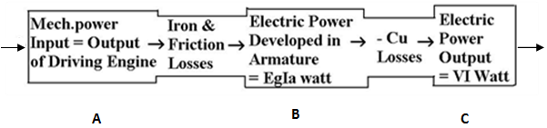
Fig. 23.6 Various losses
Mechanical Efficiency
Mechanical losses = Iron + Friction losses
![]()
Electrical Efficiency
![]()
Overall Efficiency
![]()
In general generator efficiency = Output / (Output +
losses)
The condtion for maximum efficiency of generator is
given by
![]()
i.e
Variable loss = Constant loss.