Module 6. D.C. machines
Lesson 26
STARTING AND SPEED CONTROL OF D.C. MOTORS
26.1 Need for D.C. Motor Starter
At the time of starting of motor it is at rest and no back e.m.f. is generated. On application of full voltage, armature winding draws a heavy current due to small armature resistance. This high armature current may damage the armature windings, commutator and brushes. To prevent high armature current during the starting of motors, variable resistance is connected in series with the armature winding. The starting resistance is reduced as the motor speeds up. The resistance is cut off fully when the motor attains full speed. This arrangement is known as starter. For very small D.C. motor (e.g. 6v, 12v, motor) starter is not required and it can be started directly. A D.C. Motor starter consists of:
a) External resistance – External resistance is placed in the armature circuit to limit the starting current drawn by the motor. As the motor accelerates the resistance is gradually removed.
b) No-volt release coil – In case of power failure the starter arm is brought back to the off position.
c) Overload release coil – In case of overloading of motor or any fault the starter circuit is switched off by overload release coil mechanism.
26.2 Types of Starters
1. Three point starter
2. Four point starter
3. Two point starter
26.2.1 Three point starter
Three point starters have three terminals:
i) Armature terminals A – It is connected to one of the armature winding ends.
ii) Field terminal Z – is connected to one of the field winding of the motor.
iii) Line terminal L – is connected to any of +ve or –ve wire coming from the d.c. source.
26.2.1.1 Operation of the d.c. motor starter
The incoming power is indicated as L1 and L2. The components within the broken lines form the three-point starter (Fig. 26.1). As the name implies there are only three connections to the starter. The connections to the armature are indicated as A1 and A2. The ends of the field (excitement) coil are indicated as F1 and F2. In order to control the speed, a field rheostat is connected in series with the shunt field. One side of the line is connected to the arm of the starter (represented by an arrow in the diagram). The arm is spring-loaded so, it will return to the "Off" position when not held at any other position. On the first step of the arm, full line voltage is applied across the shunt field. Since the field rheostat is normally set to minimum resistance, the speed of the motor will not be excessive; additionally, the motor will develop a large starting torque.
· The starter also connects an electromagnet in series with the shunt field. It will hold the arm in position when the arm makes contact with the magnet.
· Meanwhile that voltage is applied to the shunt field, and the starting resistance limits the current to the armature.
· As the motor picks up speed counter-emf is built up; the arm is moved slowly to short.

Fig. 26.1 Three point starter
26.2.1.2 Limitation
No-volt release coil is connected in series with the field circuit. While exercising speed control through field regulator, the field current may be weakened to such an extent that no-volt release coil may not be able to keep the starter lever in the ON position. This may disconnect the motor from the supply when it is not desired. This limitation is over come in four point starter.
26.2.2 Four point starter
(i) In a four-point starter, the no-volt release is connected directly across the supply line through a protective resistance R.
(ii) Now the no-volt release coil circuit is independent of the shunt field circuit. Therefore, proper speed control can be exercised without affecting the operation of non-volt release coil.
(iii) The only difference between a three-point starter and a four-point starter is that of the method in which no-volt release is connected. However, the working of the two starters is the same.
(iv) It may be noted that the three point starter also provides protection against an open field circuit. This protection is not provided by the four-point starter. But the possibility of open field circuit is quite remote.
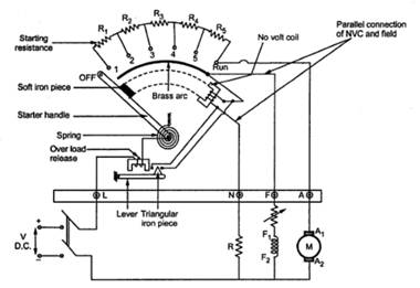
Fig. 26.2 Four point starter
26.2.3 Two point starter
1. Two point starter is used only for D. C. series motor. The basic construction of two point starter is similar to that of three point starter except the fact that it has two terminals namely line (L) and field (F).
2. The terminal F is at one end of the series combination of field and the armature winding. The action of the starter is similar to that of three point starter.
3. The main problem in case of D. C. series motor is it’s over speeding action when the load is less.
4. This can be prevented using two point starters. The no-volt coil is connected in series with the motor so both currents are equal.
5. At no load situation, load current drawn by the motor decreases. At very low current no-volt coil is demagnetized and it releases the handle to OFF position.

Fig. 26.3 Two point starter