Module 7. Electrical measuring instruments
Lesson 30
ENERGY MEASUREMENT
30.1 Introduction
It is important to understand power and power measuring method before starting energy measurement. Power and energy are related but are different. Power is the rate at which energy is transferred, used, or transformed. For example, the rate at which a light bulb transforms electrical energy into heat and light is measured in watts—the more wattage, the more power, or equivalently the more electrical energy is used per unit time. The instantaneous electrical power P delivered to a component is given by
P(t) = V(t) × I(t)
Where,
P(t) = instantaneous power, measured in watts (joules per second)
V(t) = potential difference (or voltage drop) across the component, measured in volts
I(t) = current through it, measured in amperes
30.2 Power Measurement in 3-Phase Circuits
Power in a 3-phase load (star or delta connected) can be measured in the following methods:
30.2.1 Three-wattmeter method
Fig 30.1 shows three watt meters connected in the following manner:
· Current coil is connected to one line
· Potential coil is connected between that line and some common point.
The sum total of the readings of the three watt meters gives the total power consumed. This method can be used with balanced and unbalanced load. If neutral wire is available then common point should be at the neutral wire.
Total power = W1+W2+W3
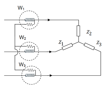
Fig. 30.1 Connection diagram for three wattmeter method
30.2.2 Two-wattmeter method
Two watt meters are connected (Fig. 30.2) such that:
· Current coils of two watt meters are connected in any two lines and
· Potential coil of each joined to the third line.
The sum total of the readings of the two watt meters gives the total power consumed. This method can be used with balanced and unbalanced load. Precaution in this method is that if neutral wire is available it should not carry any current. And if it is not so then the neutral of the load should be disconnected from the neutral of the source.
Total power = W1+W2
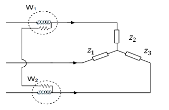
Fig. 30.2 Connection diagram for two wattmeter method
From the two wattmeter readings ϕ and thus load power factor Cos ϕ can be determined by the following equation:
![]()
Where,
W1 = Watt meter reading (Lower value)
W2 = Watt meter reading (Higher value)
Thus,
Power factor (pf) = Cos ϕ
30.2.3 One-wattmeter method
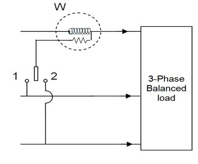
Fig. 30.3 Connection diagram for one wattmeter method
One wattmeter method is applicable to balanced load. The total circuit power is given by multiplying the wattmeter reading by three. Advantage of this method is simplicity in connection. The current coil of the wattmeter is connected in any one line and the potential coil is connected alternately between this and the other two lines. Sum of the two readings gives the total power taken up by the load.
30.3 Energy Measurement
The energy meter is an electrical measuring device, which is used to record Electrical Energy Consumed over a specified period of time in terms of units. Electricity meters operate by continuously measuring the instantaneous voltage (volts) and current (amperes) and finding the product of these to give instantaneous electrical power (watts) which is then integrated against time to give energy used (joules, kilowatt-hours etc.).
1. Voltage coil - many turns of fine wire encased in plastic, connected in parallel with load.
2. Current coil - three turns of thick wire, connected in series with load.
3. Stator - concentrates and confines magnetic field.
4. Aluminum rotor disc.
5. Rotor brake magnets.
6. Spindle with worm gear.
7. Display dials - note that the 1/10, 10 and 1000 dials rotate clockwise while the 1, 100 and 10000 dials rotate counter-clockwise.

Fig. 30.4 Energy meter
30.3.1 Electromechanical meters
The most common type of electricity meter is the electromechanical induction watt-hour meter. The electromechanical induction meter operates by counting the revolutions of an aluminium disc which is made to rotate at a speed proportional to the power. The number of revolutions is thus proportional to the energy usage. It consumes a small amount of power, typically around 2 watts.
The metallic disc is acted upon by two coils. One coil is connected in such a way that it produces a magnetic flux in proportion to the voltage and the other produces a magnetic flux in proportion to the current. The field of the voltage coil is delayed by 90 degrees using a lag coil. This produces eddy currents in the disc and the effect is such that a force is exerted on the disc in proportion to the product of the instantaneous current and voltage. A permanent magnet exerts an opposing force proportional to the speed of rotation of the disc. The equilibrium between these two opposing forces results in the disc rotating at a speed proportional to the power being used. The disc drives a register mechanism which integrates the speed of the disc over time by counting revolutions, much like the odometer in a car, in order to render a measurement of the total energy used over a period of time. The type of meter described above is used on a single-phase AC supply. Different phase configurations use additional voltage and current coils.
The aluminum disc is supported by a spindle which has a worm gear which drives the register. The register is a series of dials which record the amount of energy used. The dials may be of the cyclometer type, an odometer-like display that is easy to read where for each dial a single digit is shown through a window in the face of the meter, or of the pointer type where a pointer indicates each digit. With the dial pointer type, adjacent pointers generally rotate in opposite directions due to the gearing mechanism.
The amount of energy represented by one revolution of the disc is denoted by the symbol kWh which is given in units of watt-hours per revolution. Three-phase electromechanical induction meter, metering 100 A 230/400 V supply. Horizontal aluminium rotor disc is visible in center of meter.
In an induction type meter, creep is a phenomenon that can adversely affect accuracy, that occurs when the meter disc rotates continuously with potential applied and the load terminals open circuited. A test for error due to creep is called a creep test.
30.3.2 Electronic meters
Electronic meters display the energy used on an LCD or LED display, and can also transmit readings to remote places. In addition to measuring energy used, electronic meters can also record other parameters of the load and supply such as maximum demand, power factor and reactive power used etc. They can also support time-of-day billing, for example, recording the amount of energy used during on-peak and off-peak hours.