Module 3. Pressure measuring device
Lesson 6
MICRO MANOMETERS AND INCLINED MANOMETER
6.1 Introduction
Micro-manometers and inclined manometers are modified forms of simple U-tube manometer.
6.2 Micro-Manometer
Micro-manometer is also known as single column manometers. The construction of a micro-manometer is as follows:
a. One limb of manometer is a tank of large cross sectional area as compared to the cross sectional area of the other limb.
b. This tank acts as a reservoir to hold the manometer fluid.
c. The cross sectional area of the tank is 100 times greater than that of the other limb.
d. When there is change in the pressure in the pipe, there is negligible change in the level of fluid in tank. This change can be neglected and pressure can be measured as height of liquid in the other column.
It is of two types:
i. Vertical column micro-manometer
ii. Inclined column micro-manometer
6.3 Vertical Column Micro-manometer
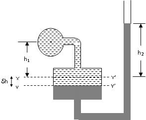
Fig. 6.1 Vertical column micro-manometer
Initially, when there is no fluid flowing in the pipe the level of manometer liquid is at XX’. But due to liquid pressure in the pipe the level of manometer liquid moves down from XX’ to YY’ in the tank and rises in the right limb to the distance h2 from XX’.
Let,
ρ1 = density of liquid for which pressure has to be determined
ρ2 = density of manometer liquid (assume mercury)
S1 = Specific gravity of liquid for which pressure has to be determined
S2 = Specific gravity of manometer liquid
δh = Fall in the level of liquid in the tank
A = Area of cross-section of the tank
a = Area of cross-section of the right limb
h = Pressure head of fluid in the pipe (as head of water)
Let ‘h’ be the pressure in terms of height of fluid in the pipe.
‘h1’ is the distance from the datum line XX’ to the centre of pipe
‘h2’ is the height of heavy liquid from the datum line XX’ in the right limb
The rise in the manometer fluid in the right limb will be equal to the fall of level in the tank.
Therefore:
δhA=a.h2
![]() ……… (i)
……… (i)
Pressure in the left limb at
YY’ = ![]()
Pressure in the right limb
at YY’= ![]()
According to Pascal’s law,

If the cross sectional area of the tank A is very large compared to cross sectional area of the right limb then i.e. A >> a, then,
Ratio of a/A will be zero and the above equation can be re-written as:
![]()
6.4 Inclined column Micro-manometer
Inclined manometers are more sensitive than vertical column manometers. Initially, when there is no fluid flowing in the pipe the level of manometer liquid is at XX’. But due to liquid pressure in the pipe the level of manometer liquid moves down from XX’ to YY’ in the tank and rises in the right limb to the distance h2 from XX’.

Fig. 6.2 Inclined column micro-manometer
Let,
S1 = Specific gravity of liquid for which pressure has to be determined
S2 = Specific gravity of manometer liquid
δh = Fall in the level of liquid in the tank
A = Area of cross-section of the tank
a = Area of cross-section of the right limb
h = Pressure head of fluid in the pipe (as head of water)
‘h1’ is the distance from the datum line XX’ to the centre of pipe
‘h2’ is the height of heavy liquid from the datum line XX’ in the right limb
![]() = length of manometer fluid along the right limb
= length of manometer fluid along the right limb
The rise in the manometer fluid in the right limb will be equal to the fall of level in the tank.
From equation for vertical column micro-manometer we have:

And since h2 = l Sin α
![]()