Site pages
Current course
Participants
General
MODULE 1.
MODULE 2.
MODULE 3.
MODULE 4.
MODULE 5.
MODULE 6.
MODULE 7.
MODULE 8.
MODULE 9.
MODULE 10.
MODULE 11.
MODULE 12.
MODULE 13.
MODULE 14.
MODULE 15.
MODULE 16.
MODULE 17.
MODULE 18.
MODULE 19.
LESSON 12. Transistor amplifier- h parameter-benefits-h parameter equivalent circuit for CE configurates- comparison.
Small Signal – Low Frequency h – Parameter Model
Let us consider transistor amplifier as a block box as shown in the Fig. 12.1.
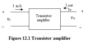
Here, Ii : is the input current to the amplifier
Vi : is the input voltage to the amplifier
Io : is the output current to the amplifier and
Vo : is the output voltage to the amplifier
As we know transistor is a current operated device, input current is an independent variable. The input current, Ii and output voltage Vo devices the input voltage Vi as well as the output current Io. Hence input voltage Vi and outpur current Io are the dependent variables, whereas input current Ii and output voltage Vo are independent variables. Thus we can write
Vi = f1 (Ii, Vo) ... (1)
Io = f2 (Ii, Vo) … (2)
This can be written in the equation form as follows
Vi = h11 Ii + h12 Vo ... (3)
Io = h21 Ii + h22 Vo ... (4)
The above equations can also be written using alphabetic notations,
Vi = hi . Ii + hr . Vo ... (5)
Io = hf . Ii + ho . Vo ... (6)
Definitions of h – parameter
The parameters in the above equation are defined as follows:
h11 = ![]() = input resistance with output short – circuited, in ohms..
= input resistance with output short – circuited, in ohms..
h12 = ![]() = Fraction of output voltage at input with input open circuited.
= Fraction of output voltage at input with input open circuited.
This parameter is ratio of similar quantities, hence unitless
h21 =  = Forward current transfer ratio or current gain with output
short circuited.
This parameter is a ratio of similar quantities, hence unitless.
h22 = ![]() = Output admittance with input open-circuited, in mhos.
= Output admittance with input open-circuited, in mhos.
From the above discussion we can say that, these four parameters are not same. They have different units. In other words, they are mixture of different units and hence referred to as hybrid parameters. As we use small letter for ac analysis, these are commonly known as h-parameters. The standard notations can be given as
i = 11= input o = 22 = output
f = 21 = forward transfer r = 12 = reverse transfer
Thus we can write h-parameters as follows.
a) With output short circuited :
h11 = hi : Input resistance
h21 = hf : Short circuit current gain
b) With input open circuited :
h12 = hr : Reverse voltage transfer ratio
h22 = ho : output admittance.
H- parameter equivalent circuit for transistor is shown in the following figure
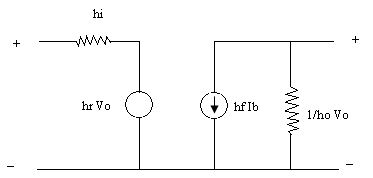
In order to analyze transistorized amplifier circuit and calculate its input impedance, output impedance, current gain and voltage gain, it is necessary to replace transistor circuit with its equivalent. The equivalent circuit can be drawn with the help of two equations, as shown in Fig. 1.10.
Vi = hi Ii + hr Vo Io = hf Ii + ho Vo
Many transistor models have been proposed, each one having its advantages and disadvantages. The transistor model used in this text is in terms of h-parameters.
Benefits of h-parameters
-
Real numbers at audio frequencies.
-
Easy to measure.
-
Can be obtained from the transistor static characteristics curves.
-
Convenient to use in circuit analysis and design.
-
Most of the transistor manufacturers specify the h-parameters.
H – parameters equivalent circuit for CE configuration in the following figure
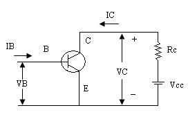 Simple common emitter configuration
To see how we can derive a hybrid model for a transistor, let us consider the common emitter configuration as shown in the above figure.. The variables Ib, Ic, Vb and Vc represent total instantaneous currents and voltages.
Ib = input current
Ic = output current
Vbe = input voltage
Vce = output voltage.
The following figure shows the h-parameter equivalent circuit for the common emitter configuration.
h-parameter equivalent circuit for the common emitter configuration
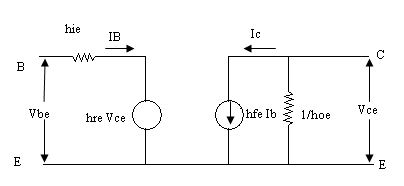
From the h-parameter equivalent circuit of the common emitter configuration we can write,
Vbe = hie Ib + hre Vce …(7)
Ic = hfe Ib + hoe Vce …(8)
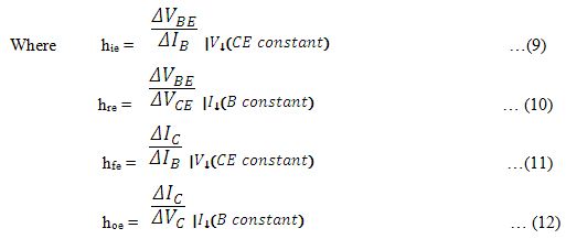
The quantities ∆VBE (Vbe), ∆VCE (Vce), ∆IB (Ib) and ∆IC (Ic) represent the small change in base and collector voltages and currents.
H-parameters for all three configurations
As mentioned earlier, transistor can be represented as a two port network by making any one terminal common between input and output. Since there are three possible configurations in which a transistor can be used, there is a change in terminal voltage and current for different transistor configurations. For different configurations the relation between input parameters and output parameters also differs. Therefore, one needs to define different set of h-parameters for different configurations. To designate the type of configuration another subscript is added to the h-parameters.
For example :
hie = h11e = input resistance in common emitter configuration.
hfb = h21b = short-circuit current gain in common base configuration.
The following table summarizes the h-parameters for all the three configurations.
|
parameter |
CB |
CE |
CC |
|
Input resistance |
hib |
hie |
hic |
|
Reverse voltage gain |
hrb |
hre |
hrc |
|
Forward transfer current gain |
hfb |
hfe |
hfc |
|
Output admittance |
hob |
hoe |
hoc |
Last modified: Wednesday, 4 December 2013, 11:15 AM