Site pages
Current course
Participants
General
MODULE 1.
MODULE 2.
MODULE 3.
MODULE 4.
MODULE 5.
MODULE 6.
MODULE 7.
MODULE 8.
MODULE 9.
MODULE 10.
MODULE 11.
MODULE 12.
MODULE 13.
MODULE 14.
MODULE 15.
MODULE 16.
MODULE 17.
MODULE 18.
MODULE 19.
LESSON 17. Application of operated amplifier-Summing-Integrating-Differentiating amplifier
Summing amplifier
The summing amplifier provides an output voltage equal to the algebraic sum of the input voltages.
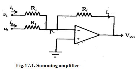
Fig.17.1 shows an inverting amplifier, used to sum two input voltages. The input voltages v1 and v2 are applied through the resistors R1 and R2 to the summing junction (P) and Rf is the feedback resistor. At the point P,
i1 + i2 = if
Since the voltage at the point P is ideally 0,
(V1 / R1) + (V2/R2) = Vout / Rf
Hence the output voltage,
Vout = (Rf / R1) V1 + (Rf / R2)V2
If R1 = R2 = Rf = Rv then Vout = - (V1 + V2)
Hence the output voltage is equal to the sum of the input voltages and the circuit acts as a summing amplifier. The negative sign indicates than OP-AMP is used in the inverting mode.
Difference amplifier
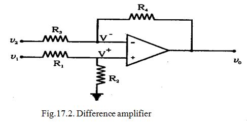 The difference amplifier is shown in Fig.17.2. The output voltage can be obtained by using superposition principle. To find the output voltage V01 due to V1 alone, assume that V2 is shorted to ground. Then
V+ = [R2 / (R1 + R2)] V1
And V01 = [(R3 + R4) / R3] V+ = [(R3 + R4) / R3] [R2 /( R1 + R2)] V1
Now assuming that V1 is shorted to ground, the output voltage V02 due to V2 alone is given by
V02 = (R4/R3) V2
Therefore, with both inputs present, the output is
V0 = V01 + V02
= [(R3 + R4) / R3] [R2 / (R1 + R2)] V1 – (R4/R3)V2
If R1 = R2 = R3 = R4 = R
Then Vo = V1 – V2
If all the external resistors are equal, the voltage difference amplifier functions as a voltage subtractor.
Integrating amplifier
If a capacitor is inserted in the feedback path, we got an output, which is the time, integral of the input signal. Figure 17.3 (a) shows the circuit and Fig.17.3 (b) shows the equivalent circuit (with virtual ground).
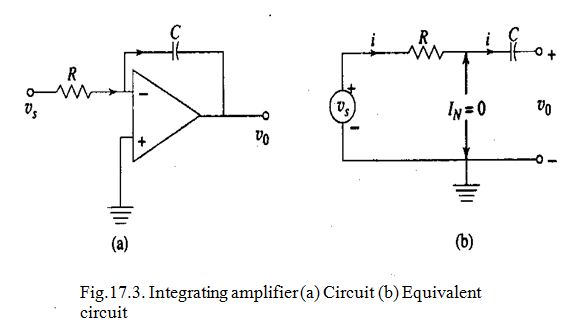
Thus, the output voltage is proportional to the integral of input voltage.
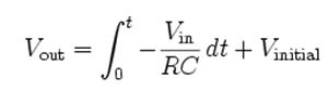
If the input voltage is constant, i.e., Vin = Vs = V, the output will be –Vt/RC which is a ramp. Thus, the circuit of Fig 17.3 (a) can be used as a ramp generator.
Differentiating amplifier
The insertion of a capacitor in the input path and resistor in the feed back path (Fig.17.4 (a)) gives a differentiating amplifier. Figure17.4 (b) shows the equivalent current.
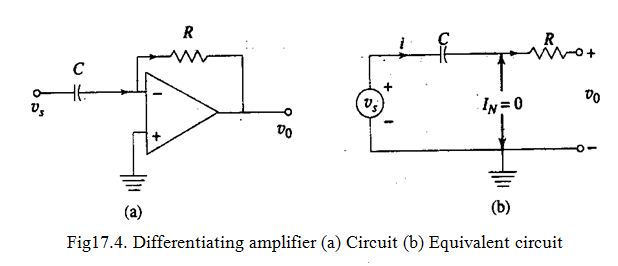
Where, Vin = Vs is the input voltage.
Last modified: Saturday, 5 October 2013, 10:15 AM