Site pages
Current course
Participants
General
MODULE 1.
MODULE 2.
MODULE 3.
MODULE 4.
MODULE 5.
MODULE 6.
MODULE 7.
MODULE 8.
MODULE 9.
MODULE 10.
MODULE 11.
MODULE 12.
MODULE 13.
MODULE 14.
MODULE 15.
MODULE 16.
MODULE 17.
MODULE 18.
MODULE 19.
LESSON 25. Basic input circuits-Active and passive transducer-Error-types-calibration.
Basic input circuits
The output available from the sensor or transducer is often not compatible with the desired transmission system or display unit. This can be made to be so by appropriate signal conditioning and processing of data thereafter. Depending on the type and mode of the output from the sensor, the intermediate stage of conditioning of signal is decided. There may be a number of units in this conditioning stage. A very simple instrumentation system is represented in the figure.
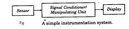
The manipulating unit consists mainly of a conversion circuit (a bridge circuit), an amplifier, if necessary an impedance matching circuit, for transmission a modulation circuit and a detector fro display. All units are not always necessary and sometimes some more and different units are needed.
The present day trend is to convert the sensor output into an electrical signal first whatever be the form of its original output as conditioning and data processing are much more convenient by electrical means.
Basic input circuits (Interfacing circuits)
Interfacing circuit or input circuit is an electrical circuit that interfaces the sensor/transducer (where electrical output is available) with the more demanding signal conditioning equipment like amplifier, modulator, processor, etc. There are a number of such circuits performing appropriate functions in the interfacing stage. One major reason of such circuits is that the transducer may be a passive type and requires an auxiliary source of energy for giving a signal in voltage or in current. As mentioned earlier, bridge circuit is a very common interfacing circuit. There are others like ballast circuits current sensitive circuits, voltage divider circuits etc.
Current sensitive circuit
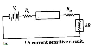
It is basically a series circuit of the voltage supply, a current indicating/recording device and the transducer of the resistance type. The supply source has a internal resistance Rs. The meter has a resistance Rm and the transducer resistance may vary between 0 and R (say) – let it be represented by kR when 0 £ k £1. The circuit schematic is shown in Fig. 13.2. The meter current at any stage is i with a maximum of ix.
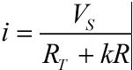
Let Rm + Rs = RT then the circuit current is given by
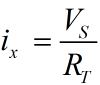
The maximum current occurs when k = 0, so that
giving the ratio
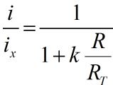
The output, I is a function of ix i.e. of VS and it should be maintained constant. The sensitivity of the system increases with increasing R/RT i.e. system is nonlinear.
Ballast circuit
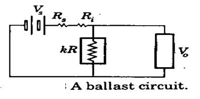
It is a voltage sensing circuit instead of the current sensing type. The scheme is shown in Fig. 13.3. Vs is the supply voltage, Rv is the supply or voltage source resistance, V0 is the supply voltage, Rv is the supply or voltage source resistance, Vo is the voltage indicated or recorded for a variation in R again given as kR, Ri is a resistance introduced in the position as shown and Ri >> Rs. The resistance Ri is known as the ballast resistance.
For the voltmeter having a very high resistance, current through Ri + Rs is
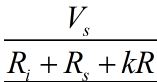
and the voltage across kR is also the output voltage Vo
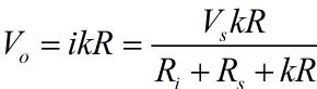
or
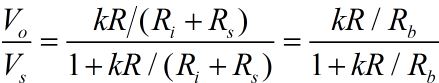
With change in measurand k changes so that change in Vo with k is given by
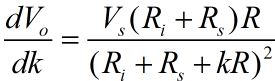
There is, however, an optimum choice of Ri (or, Ri + Rs = Rb say) for which sensitivity can be made maximum. By differentiating Vo with respect to Rb, this is obtained as
Rb = kR
Obviously, this also varies with sensor output resistance
Loading Error
If the voltmeter draws a current, there is an error in measurement called the loading error. If the meter has a resistance Rm then the total resistance seen by the source Vs is
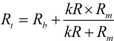
and the current is now
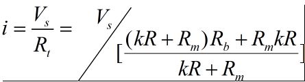
so that the output voltage is now
Vo = Vs - iRb
=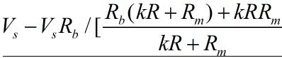
=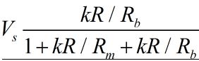
By taking the difference one can show that
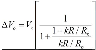
so that the % error is
E% =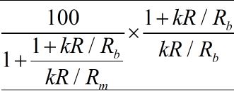
It is worthwhile to note that (percentage) error also is a function of k.
Bridge Circuits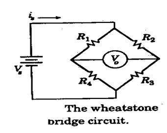
The most common interfacing circuit between a passive sensor and the measurement system is the bridge circuit. Wheatstone bridge is a circuit that is extensively used till today although it was devised as early as 1833. A lot of variation has since been in operation of this bridge without altering the basic structure which is shown in Figure.
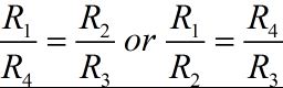
The resistance bridge supply is Vs and output Vo. Solving for Vo = 0, the condition in terms of R1, R2, R3 and R4 is obtained as
This is called the null-balance bridge. It is possible to take output Vo for different values of resistance. It is initially balanced satisfying the above condition and subsequently the unbalanced voltage is measured b a voltmeter of very high impedance. However, alternative to this, a current meter may also be connected and response observed.
For voltage detector scheme with very high impedance of the detector and R4 as the sensor resistance that changes to R4 + DR4 and initially with R1 = R2 = R3 = R4 = R one derives.
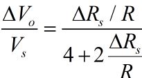
which changes to
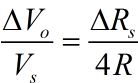
for DRs<<R.
If, instead, a galvanometer is used as a detector with its resistance Rg often chosen to be equal to Rv and, again with all R/s equal initially to R, one derives the incremental detecting current through the galvanometer for an incremental change in R1 equal to DR1 say, and is given as

where ig is the current supplied by the source.
Bridge circuits have been used in ac operation for resistance, capacitance as well as inductance measurement. Impedance bridges, as they are called, are listed in figure
Active and passive transducers
To perform all the general functions, a physical component may act as an active transducer or a passive transducer.
A component whose output energy is supplied entirely or almost entirely by its input signal is commonly called a passive transducer. The output and input signals may involve energy of the same from or there may be an energy conversion from one form to another farm.
An active transducer has an auxillary source of power which supplies a major part of the output while the input signal supplies only an insignificant portion.
Error Analysis
Types of Errors
a) Gross errors- largely human errors, among them misreading of instruments, incorrect adjustment and improper application of instruments and computational mistakes.
b) Random errors –those errors that cannot be directly established because of random variations in the parameter or the system of measurement.
c) Systematic errors- Shortcomings of the instruments such as defective or worn parts and effects of the environment on the equipment or the user.
Types of systemic errors
- Instrumental errors
- Environmental errors
- Static errors
- Dynamic errors
The uncertainty in the final result is due to the uncertainties in the primary measurements. This may be done by a commonsense analysis of the data which may take many forms. One rule of thumb that could be used that the error in the result is equal to the maximum error in any parameter used to calculate the result. Another commonsense analysis would combine all the errors in the most detrimental way in order to determine the maximum error in the final result. Consider the calculation of electric power from
P=EI
Where E and I are measured as
E=100V±2V
I=10A±0.2A
The nominal value of the power is 100*10=1000W.by taking the worst possible variations in the voltage and current, we could calculate
Pmax= (100+2) (10+0.2) =1040.4W
Pmin= (100-2) (10-0.2) =960.4W
Thus, using this method of calculation, the uncertainty in the power is +4.04 percent,-3.96%.it is quite unlikely that the power would be in the error by these amounts because the voltmeter variations would probably not correspond with the ammeter variations. when the voltmeters reads an extreme “ high” there is no reason that the ammeter must also read an extreme “high” at that particular instant, indeed, this combination is most unlikely.
Calibration
Calibration: To check the instrument against a known standard and subsequently to reduce errors in accuracy
Calibration procedures involve a comparison of the particular instrument with either a primary standard or a known input source.
NIST-This institute defines the standard for length, mass, time, temperature and force.
Static calibration -All the static performance characteristics are obtained in one form or another by a process called static calibration. All working instruments must be calibrated against some reference instruments which have a higher accuracy.
Error calibration-Error calibration means that an instrument has been calibrated against a suitable standard.
Last modified: Thursday, 5 December 2013, 8:07 AM