Site pages
Current course
Participants
General
MODULE 1.
MODULE 2.
MODULE 3.
MODULE 4.
MODULE 5.
MODULE 6.
MODULE 7.
MODULE 8.
MODULE 9.
MODULE 10.
MODULE 11.
MODULE 12.
MODULE 13.
MODULE 14.
MODULE 15.
MODULE 16.
MODULE 17.
MODULE 18.
MODULE 19.
LESSON 26. Relative displacement, translational and rotational transducer-calibration
INTRODUCTION
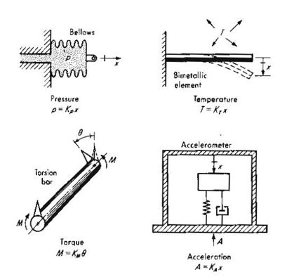
We consider here devices for measuring the translation along a line of one point relative to another and the plane rotation about a single axis of one line relative to another. Such displacement measurements are of great interest as such and because they form the basis of many transducers for measuring pressure, force, acceleration, temperature, etc., as shown in the following figure
CALIBRATION
Static calibration of translational devices often can be satisfactorily accomplished by using ordinary dial indicators or micrometers as the standard. When used directly to measure the displacement of the transducer, these devices usually are suitable to read to the nearest 0.0001 in or 0.01 mm. If smaller increments are necessary, lever arrangements (about a 10:1 ratio is fairly easy to achieve) or wedge-type mechanisms (about 100:1) can be employed for motion reduction. The Mikrokator, a unique mechanical gage of high sensitivity, may also be useful in measuring small motions down to a few millionths of an inch.
If accuracy to 0.0001 in or better is required, such equipment should itself be calibrated against gage blocks, or (for maximum accuracy) gage blocks of hard, used directly to calibrate the transducer. Gage blocks are small blocks of hard, dimensionally stable steel or other material, made up in sets which can be stacked up to provide accurate dimensions over a wide range and in small steps. They are the basic working length standards of industry. As purchased from the manufacturer, their dimensions are accurate to ± 8 μin for working grade blocks, ± 4 μin for reference grade, and 2 μin for all blocks up to 1 in (± 2 μin / in for blocks longer than 1 in) for master blocks. If these tolerances are too large, the blocks can be sent to NIST and calibrated against light wavelengths to the nearest 10 – 7 in. Some precision – manufacturing operations currently require and use the latter calibration service. When transducers are calibrated to very high accuracies, it is extremely important to control all interfering and/or modifying inputs such as ambient temperature, electrical excitation to the transducer, etc.
Rotational or angular displacement is not itself a fundamental quantity since it is based on length, and so a fundamental standard is not necessary. However, reference and working standards for angles (and thus angular displacement) are desirable and available. The basic standards (against which other standards or instruments) may be calibrated are called angle blocks. These are carefully made steel blocks about 5/8 in wide and 3 in long, with a specified angle between the two contact surfaces. Just as for length gage blocks, these angle blocks can be stacked to “build up” any desired angle accurately and in small increments. The blocks can be calibrated to an accuracy of 0.1 second of arc by NIST.
Rotational transducers rarely require such accuracy for calibration, nor can the laborious and expensive techniques necessary to realize these limits be economically justified. Thus most static calibration of angular – displacement transducers can be adequately carried out by using more convenient and readily available equipment. Examples of such equipment which should be available in a precision machine shop are the circular division taster (range 360o, microscope reads to 0.1 minute of arc, precision of scale disk ± 20 seconds of arc), the optional dividing head (range 360o, scale reads to 1.0 minute of arc, working accuracy ± 20 seconds of arc), the optical dividing head (range 360o, scale reads to 1.0 minute of arc, working accuracy ± 20 seconds of arc), and the division tester with telescope and collimator (accuracy ± 2 seconds of arc). In some applications, even cruder devices such as ordinary machine-tool index heads, calibrated dials, etc., may be perfectly adequate.
RESISTIVE POTENTIOMETERS
Basically, a resistive potentiometer consists of a resistance element provided with a movable contact. The contact motion can be translation, rotation, or a combination of the two (helical motion in a multiturn rotational device), thus allowing measurement of rotary and translatory displacements. Translatory displacements. Translatory devices have strokes from about 0.1 to 20 in and rotational ones range from about 10o to as much as 60 full turns. The resistance element is excited with either dc or ac voltage, and the output voltage is (ideally) a linear function of the input displacement. Resistance elements in common use may be classified as wire-wound, conductive plastic, hybrid, or cermet.
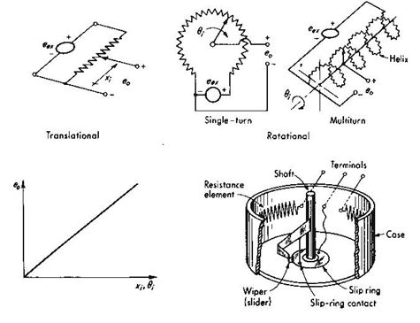
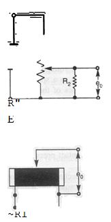
If the distribution of resistance with respect to translational or angular travel of the wiper (moving contact) is linear, the output voltage eo will faithfully duplicate the input motion xi or θi if the terminals at eo are open-circuit (no current drawn at the output). (For ac excitation, xi or θi amplitude-modulate eex , and eo does not look like the input motion.) The usual situation, however, is one in which the potentiometer output voltage is the input to a meter or recorder that draws some current from the potentiometer. Thus a more realistic circuit is as shown in fig. Analysis of this circuit gives
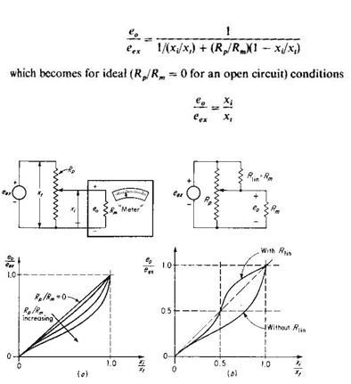
thus for no “loading” the input –output curve is a straight line. In actual practice, Rm ≠ α and Eq.(4.1) shows a nonlinear relation between eo and xi. This deviation from linearity is shown in Fig.4.5a. The maximum error is about 12 percent of full scale if Rp / Rm = 1.0 and drops to about 1.5 percent when Rp/Rm = 0.1. For values of Rp / Rm < 0.1, the position of maximum error occurs in the neighbourhood of xi/xt = 0.67, and the maximum error is approximately 15 Rp / Rm percent of full scale.
We see that to achieve good linearity, for a “meter” of a given resistance Rm , we should choose a potentiometer of sufficiently low resistance relative to Rm. This requirement conflicts with the desire for high sensitivity. Since eo is directly proportional to eex , it would seem possible to get any sensitivity desired simply by increasing eex. This is not actually the case, however, since potentiometers have define power ratings related to their heat-dissipating capacity. Thus a manufacturer may design a series of potentiometers, say single-turn 2-in-diameter, with a wide range (perhaps 100 to 100,000 Ω) of total resistance Rp, but all these will be essentially the same size and mechanical configuration, giving the same heat-transfer capability and thus the same power rating, say about 5 W at 20oC ambient. If the heat dissipation is limited to P watts, the maximum allowable excitation voltage is given by
max eex = √ PRp
 Thus a low value of Rp allows only a small eex and therefore a small sensitivity. Choice of Rp Thus must be influenced by a tradeoff between loading and sensitivity considerations. Thus maximum available sensitivity of potentiometers varies considerably from type to type and also with size in a given type. It can be calculated from the manufacturer’s data on maximum allowable voltage, current, or power and the maximum stroke. The shorter-stroke devices generally have higher sensitivity. Extreme values are of the order of 15 V/deg for short-stroke rotational types (“sector” potentiometers) and 300 V/in for short-stroke (about ¼ in) translational pots. It must be emphasized that these are maximum values and that the usual application involves a much smaller (10 to 100 times smaller) sensitivity. Fig. 4.5b shows a method for improving linearity without increasing Rm.
CALIBRATION
The measurement of rotational (angular) velocity is probably more common than that of translational velocity. Since translation generally can be obtained from rotation devices. For angular and linear velocities, perhaps the most convenient calibration scheme uses a combination of a toothed wheel, a single magnetic proximity pickup and an electronic EPUT (Events per unit time) meter .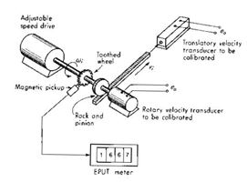 The angular rotation is provided by some adjustable-speed drive of adequate stability. The toothed iron wheel passing under the proximity pickup produces an electric pulse each time one tooth passes. These pulses are fed to the EPUT meter, which counts them over an accurate period (say 1.00000 s), displays the result visually for a few seconds to enable reading, and then repeats the process. The stability of the rotational drive is easily checked by observing the variation of the EPUT meter readings from one sample to another. The inaccuracy of pulse counting is ± 1 pulse plus the error in the counter time base, which is of the order of 1 ppm. The overall accuracy achieved depends on the stability of the motion source, the angular velocity being measured, and the number of teeth on the wheel. If the motion source were absolutely stable (no change in velocity what-ever), very accurate measurement could be achieved simply by counting pulses over a long time, since then the average velocity and the instantaneous velocity would be identical. If the motion source has some drift, however, the time sample must be fairly short. For example, a shaft rotating at 1,000 r/m with a 100-tooth wheel produces 1,667 pulses in a 1-s sample period. The inaccuracy here would be 1 part in 1,667 (the 1-ppm time-base error is totally negligible), or 0.06 percent. If the shaft rotated at 10 r/min, the error would be 6 percent. Slow rotations can be measured accurately by such means if the toothed wheel is placed on a shaft which is sufficiently geared up from the shaft driving the transducer being calibrated.
The above procedure uses relatively simple equipment and generally provides entirely adequate accuracy. Other simpler and less accurate procedures can be employed if they are adequate for their intended purpose. These usually consists of simply comparing the reading of a velocity transducer known to be accurate with the reading of the transducer to be calibrated when both are experiencing the same velocity input.
Velocity by Electrical Differentiation of Displacement Voltage Signals
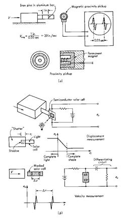 The output of any displacement transducer may be applied to the input of a suitable differentiating circuit to obtain a voltage proportional to velocity. The main problem is that differentiation accentuates any low-amplitude, high-frequency noise present in the displacement signal. Thus a carbon-film potentiometer would be preferable to the wire wound type, and demodulated and filtered signals from ac transducers may cause trouble because of the remaining ripple at carrier frequency.Workable systems using electrical differentiation are possible, however, with adequate attention to details.Displacement is the vector representing a change in position of a body or a point with respect to a reference. It may be linear or rotational motion, expressed in absolute or relative terms. Many of the modern scientific and industrial observations need a very accurate measurement of this parameter. Being a fundamental quantity, the basic sensing device is widely adapted with suitable linkages for the measurement of many derived quantities, such as force, stress, pressure, velocity, and acceleration. The magnitude of measurement ranges from a few microns to a few centimetres in the case of linear displacement and a few seconds to 3600 in the case of angular displacement. A majority of displacement transducers sense the static or dynamic displacement by means of a sensing shaft or similar links mechanically coupled to the point or body whose motion is measured. Such attachments of both linear and angular transducers are usually of simple mechanical configurations, but the coupling must be primarily designed to avoid any slippage after it is fastened and thereby keep the back-lash minimum. For linear-displacement measurements, the common types employed are the thread- ed end, lug, clevis, and bearing couplings. Spring-Ioaded shafts may also be used for certain applica- tions. A number of specialized types of displacement transducers operate without use of a mechanical linkage between the transducer and the object whose displacement is to be measured, as in the case of some of the electromagnetic, capacitive, and optical transducers.
PRINCIPLES OF TRANSDUCTION
Displacement transducers can be classified primarily on the basis of the transduction principle employed for the measurement. In this chapter only the electromechanical transducers, which convert displacement quantities into electrical voltages/currents, are dealt with.
The major electrical transduction principles used are: (i) Variable resistance-potentiometric/strain gauge
(i) Variable inductance /linear variable differential transformer/variable reluctance (iii) Variable capacitance
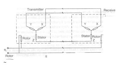
(ii) Synchros and resolvers.
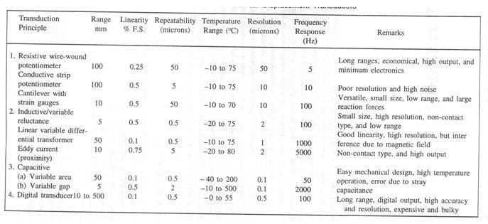
A number of additional types are also designed, depending upon the convenience and measurement accuracy required, such as digital output transducers, electro-optical devices, and the radioactive devices. In practice, potentiometric- and inductive-type devices are most widely used in scientific and engineering applications. The performance characteristics of a few selected variety displacement transducers are shown in Table
Variable Resistance Device
Displacement transducers using potentiometric variable resistance transduction elements are invariably shaft-coupled devices. The sensing element is basically a resistance-potentiometer with a movable wiper contact attached to an insulated plunger type shaft, mechanically linking the point under measurement.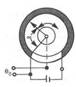 The contact motion can be translation, rotation, or a combination of the two, thus allowing measurements of rotary or translatory displacements. They are relatively simple in construction, in the sense that a sliding contact (wiper) is made to move linearly over a resistance el~ment which may be in the form of a wire or a conductive plastic film. The resistivity and temperature coefficient of the resistance element should be of such a value that the device operates with appreciable constant sensitivity over a wide temperature range. The three major elements critical in a potentiometric device are the winding wire, winding former, and wiper
Potentiometer displacement transducer. {a) linear motion; {b) angular motion; {c) circuit arrangement
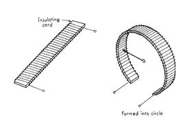
The winding wire is a precision drawn resistance wire with a diameter of about 25 to 50 microns and is wound over a cylindrical or a flat mandrel of ceramic, glass, or anodized aluminium. The wire is annealed in a reducing atmosphere to avoid any surface oxidation. Resistivity may vary normally from 0.4 ~-m to 1.3 !lQ-m, and temperature coefficient may vary from 0.002%IOC to 0.01 %loC. The wire should be strong, ductile, and protected from surface corrosion by enamelling or oxidation. The dimen- sional tolerance should be less than 1 %, and the resistance stability with time should be of a very high order. The materials commonly employed are the alloys of copper-nickel, nickel-chromium, and silver- palladium. The winding can be linear, toroidal, or helical, and should possess uniform spacing and constant tension. The outer surface, except for the linear track of the wiper, is covered with a suitable insulating material to protect against dust and abrasion.
The wipers are spring elements made from tempered phosphor-bronze, beryllium-copper, or other precious metal alloys and are suitably shaped to move over the resistance element with minimum friction. The wiper contact force and contact resistance are important factors in the overall accuracy of the device. In some cases conductive lubricants are also used to reduce the friction. Leaf spring and dual wipers are designed for better contact and ability to withstand high shocks and vibration. The main requirements for winding formers are good dimensional stability and surface insulation. Some of the recommended materials are ceramic, steatite, anodized aluminium, and moulded epoxies.
The whole transduction element described above can be employed for linear as well as angular displacement. The linear range depends very much on the mechanical design. The resistance value and the current-carrying capacity are chosen to suit the desired application; normal values are range 2 to 10 cm F.S., resistance 100 to 50,000 ohms, and current capacity 0.5 to 5 mA. The resolution of the device depends upon the wiper width, diameter of the resistance wire, and spacing between the windings. An optimum choice is sought for the highest precision and resolution. In the case of the wire wound element, the wiper wire diameter to spacing ratio is normally 10, and the resolution achievable is 0.05% to 0.1 %. A linearity of the order of 0.1% can be achieved easily, as wires of uniform diameter and specific resistance are available. The plastic.film type is ideal for infinite resolution purposes, even though it is difficult to get a resolution better than 5 microns in practice.
Electrical noise is another factor normally exhibited by these devices and they are random in nature. Further, they depend on the current and speed of motion of the wiper. Wire.wound devices are relatively free from Johnson noise. But the contact noise caused by variation in contact resistance when the wiper moves along the potentiometer track is not negligible in many cases. The noise level increases with wear and tear and also with the contamination or oxidation of the track and the wiper surfaces. Sometimes, thermoelectri~ effects due to dissimilar materials used for the wiper and wire can also generate a voltage acting as a noise source. This is particularly true when the device is operating at higher temperatures. Yet another type of noise exhibited is the vibrational noise or high.velocity noise caused by jumping or bouncing movements of the wiper. This is reduced by adjusting the contact pressure and oscillatol"y characteristics of the wiper structure.
The sensitivity of the device is normally given as volts per full-scale mechanical travel of the wiper. The input excitation voltage is limited by the dissipating wattage which causes the temperature of the winding wire to rise to a specified level. This voltage level depends upon the cooling conditions, the thermal characteristics of the potentiometer wire, and the transducer housing design.
Inherent linearity depends on the minimum resolution achievable in the device. If the apparent resolution is n% of F.S., the linearity error cannot be smaller than :t Ifm% of F.S. Further, the linearity is a function of the winding pitch, variations in wire diameter, and any irregularity in former dimensions and wiper movements. The normal value achievable for a standard unit is 0.1 %
The resistance measurement can be carried out with a simple circuitThe circuit linearity is determined by the ratio of the total potentiometer resistance R1 to the load resistance R2 as indicated in the figure.
The major disadvantages of the potentiometer-type displacement transducer are poor dynamic re- sponse, susceptibility to vibration and shock, poor resolution, and presence of noise in signal. Displacement transducers for very short stroke lengths can be designed with high precision using a bonded/unbonded strain.gauge type sensor. The motion to be measured is transferred to an elastic element, such as a cantilever beam, and the stresses developed on application of displacement is related to the motion. This principle is extended very much in the design of force, pressure, and acceleration transducers.
Variable Inductance Transducer
A simple and more popular type of displacement sensor is the variable-inductance type wherein the variation of inductance as a function of displacement is achieved either by variation in mutual inductances or self inductances. Devices operating on these principles are more widely known as linear variable differential transformers and variable reluctance sensors respectively.
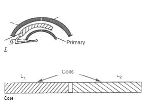
(a) Linear Variable Differential Transformer (LVDT) Linear variable differential transformer type of transducers find a number of applications in both measurement and control systems. The extremely fine resolution, high accuracy, and good stability make the device particularly suitable as a short-stroke, po~ition-measuring device. Since a number of physical quantities, such as pressure, load, and acceleration can be measured in terms of mechanical deflection. L VDT forms the basic sensing element in all such measurements. The L VDT device is widely used as the basic element in extenso- meters, electronic comparators, thickness-measuring units, and level indicators. Some of the other important applications aI.e in numerically controlled machines and creep-testing machines. The linear variable differential transformer consists of a primary coil and two identical secondary coils, axially-spaced and wound on a cylindrical-coil former, with a rod-shaped magnetic core positioned centrally inside the coil assembly providing a preferred path for the magnetic flux linking the coils. The displacement to be measured is transferred to the magnetic core through suitable linkages. When the primary coil is energized with an ac carrier wave signal, voltages are induced in each secondary section, the exact value depending upon the position of the magnetic core with respect to the centre of the coil assembly. If the core is symmetrically placed (electrically) with respect to the two secondary coils, equal voltages are induced in the two coils. When these two outputs are connected in phase opposition as shown in Fig. 4.2(b), the magnitude of the resultant voltage tends to a zero value. Such a balancepoirit is termed 'the null position'. In practice, a small residual voltage is always present at a null position due to the presence of harmonics in the excitation signal and stray capacitance coupling between the primary and secondary windings. When the core is now displaced from the null position the induced voltage in the secondary towards which the core has moved increases while that in the other secondary decreases. This results in a differential voltage output from the transformer. where f = excitation signal frequency, I, = primary current, np = number of turns in primary, n.f = number of turns in secondary. b = width of[.the primary coil, w = width of the secondary coil, x = core displacement, r = outer radius of the coil, and r. = inner radius of the coil.
With proper design of coils, the magnitude of the output signal is made to vary linearly with the mechanical displacement of the core on both sides with respect to the null position. as shown in Fig.. While the magnitude of the output voltages are ideally the same for equal core displacements on either side of the null, the phase difference between the output and input voltages changes by 1800 when the core moves through the null position. In actual measurement. this phase change-over is measured with a phase-sensitive detector. The sensitivity is proportional to the frequency f and the primary current I. and for best linearity x « b. However. larger I produces core saturation and an increase in the temGerature of the coil, and hence results in larger harinonics at null position, making adjustment difficult. An increase in frequency produces a greater effect of stray capacitance. and in turn a large null voltage. In practice, the design is optimized for the lowest null voltage, highest linearity, and appropriate size.
The coils are wound on phenolic or ceramic formers to improve the dimensional stability. The coil former material should be strong and mechanically stable to guard against temperature effects and should be able to withstand elevated temperature and thermal shock. The coils are wound with an enamelled copper wire possessing an insulation suitable for the ambient temperature specified. The transformer is then enclosed in ferromagnetic cases, providing full electro- static and electromagnetic shielding. The moving core is made of ferromagnetic material of high per- meability. selected for optimum performance in general use and heat treated to provide the best magnetic properties. The normal excitation voltage is 1.0 Vat a carrier frequency of 2 kHz to 10 kHz. The carrier frequency is suitably chosen for optimum sensitivity and proper demodulation. The dynamic response of the L VDT is limited mainly by the excitation frequency; faithful linear characteristics are obtained for frequencies up to 0.1 times the carrier frequency. The normal ranges are :t 10 microns to :t10 mm, operating over a temperature range of -40° to + 100° C. In general, the linear range is primarily dependent on the length of the primary and secondary coils. The instrumentation can be carried out with a suitable carrier wave amplifer, followed by a phase sensitive detector and a filter. as described in Chapter 12. Phase detector is invariably used in all the measurement systems to avoid the ambiguity in the direction of motion. With the availability of miniature integrated chips. it is feasible to incorporate the oscillator, the demodulator and the associated electronic circuitry within the transducer housing itself, thereby enabling the device to operate as a dc-dc system. An output voltage of 0 to 5 V can be obtained with an input supply of :t 15 V dc.
The main advantages of the LVDT type of displacement sensors are:
(i) Mechanical: Simplicity of design and ease of fabrication and installation, wide range of displace- ment; frictionless movement of core and hence infinite resolution; rugged construction; negligible operating force (core weight being low), and ability to operate even at higher temperatures.
(ii) Electrical: Output voltage is a linear and continuous function of mechanical displacement (linear- ity better than 0.25%), high sensitivity (2 mV/volt/10 microns at 4 kHz excitation); low output impedance (100 ohms); ability to operate over a wide range of carrier frequencies (50 Hz to 20 kHz); infinite resolution in output (theoretically limiting factors being signal to noise ratio and input stability conditions); and very low cross sensitivity.
(b) Angular Displacement Measurement: A rotary variable differential transformer is a very convenient device for the measurement of angular displacement. The device operates on the same principle as L VDT explained earlier, where the output yoltage varies linearly with the angular position of the shaft. A cardioid-shaped cam (rotor) of a magnetic material is used as the core. The input shaft fastened to the core is mounted at the Sec. 1 centre of the coil former on which the primary and secondary are wound symmetrically. The cardioid shape of the rotor is so chosen Core as to produce a highly linear output over a specified angle of rotation. Main advantages of the unit are infinite resolution and linear operation (better than:!: 0.5% of the full range). The signal conditioner employed here is the same as that for LVDT type transducers.
(c) Variable Reluctance Transducer: The variable reluctance type displacement sensor is very useful for certain laboratory measurements of stress, thickness, vibration, and shock. In one of the configurations, two coils Lt and L2 are wound continuously over a cylindrical bobbin with a ferromag- netic core moving within it. Any variation in the position of the core will change the self-inductances of the coils Ll and L2, as illustrated in Fig. 4.4. In another type, an E-shaped magnetic core having two windings at the end limbs is used with an armature mounted suitably covering the pole faces, with an appropriate air gap. In either case, it can be shown that the fractional change .1 L in the inductance L
Measurements are carried out with a Wheatstone's bridge network wherein the coils L1 and L2 form half of the bridge and the other two arms are completed with two fixed resistors R1 and R2 with capacitors C1 and C2 in parallel to achieve both amplitude and phase balance. The main advantages of the device are its high sensitivity and good linearity of 0.5 to 1% even for long stroke lengths of 50 cm (overall length should be double that of a stroke length). The device can be operated under severe environmental conditions, with encapsulation of the coils in an epoxy resin and hermet- ically-sealed bobbin. With appropriate modification, it can be employed for velocity and acceleration measurements also.

Displacement transducer
In the displacement transducer, mechanical elements like diaphragm, bellows, bourdon tube and single or double suspension cantilever are used to convert the applied mechanical force into displacement. These mechanical elements shown in Figure 15.1. are called force – summing devices. The displacement activated by the force – summing devices is converted into electrical signal using a transducer the resistance strain gauge, capacitive transducer, LVDT, piezolectric and photoelectric etc. The strain gauge and LVDT are dealt in detail below.
Linear variable differential transformer (LVDT)
The linear variable differential transformer (LVDT) is most widely used inductive transducer.. The LVDT consists of a primary coil (P), two identical secondary coils (S1 and S2) and a rod shaped magnetic core (A) at the centre. The magnetic core is made of nickel iron alloy and is slotted longitudinally to reduce eddy current loss. The primary coil is connected to an alternating current source. The displacement to be measured is applied to the arm attached to the core. When the core is placed symmetrically with respect to the two recording coils, equal voltages are induced in the two coils. When these two voltages are in phase opposition, the resultant becomes zero. This is called mull position of the core. When the core moves from its null position due to the displacement of the object linked mechanically to it, the voltage induced in the secondary coil (towards which the core has moved) increase, simiultaneously reducing the voltage in the other secondary winding. Thus the amount of voltage change in wither secondary winding is proportional to the amount of movement by the core. The difference of the two voltages induced in the secondary, appears across the output terminals of the transducer giving a measure of the displacement.
Advantages
-
LVDT has rugged construction and can withstand high degree of shock and vibration.
-
It consumes very less power
-
It does not possess sliding contacts and hence no friction.
-
It possesses a high sensitivity
-
It also possesses a very high resolution
-
Its output voltage is practically linear
-
It has excellent repeatability.
Disadvantages
-
LVDT is sensitive to stray magnetic field
-
The receiving instrument must be in a position to operate on a.c. signal.
-
For appreciable differential output, relatively large displacement is required.
-
Its performance is affected by temperature
-
The mass of the core and the frequency or the applied voltage limits the dynamic response of the transducer.
Uses of LVDT
Some of the major muses of LVDT are listed below
-
LVDT can be used for measuring displacements ranging from fraction of a millimetre to a few centimetres.
-
As a primary transducer, it converts the displacement directly into a proportional electric signal,
-
As a secondary transducer, it can be used to measure force with load cell as the primary transducer.
-
It can also be used to measure pressure with bourdon to be as primary transducer.
Last modified: Thursday, 5 December 2013, 8:11 AM