Site pages
Current course
Participants
General
Module 1. Average and effective value of sinusoida...
Module 2. Independent and dependent sources, loop ...
Module 3. Node voltage and node equations (Nodal v...
Module 4. Network theorems Thevenin’ s, Norton’ s,...
Module 5. Reciprocity and Maximum power transfer
Module 6. Star- Delta conversion solution of DC ci...
Module 7. Sinusoidal steady state response of circ...
Module 8. Instantaneous and average power, power f...
Module 9. Concept and analysis of balanced polypha...
Module 10. Laplace transform method of finding ste...
Module 11. Series and parallel resonance
Module 12. Classification of filters
Module 13. Constant-k, m-derived, terminating half...
LESSON 11. Reciprocity Theorem
The circuit in the figure is a concrete example of reciprocity. The reader should solve the circuit, and determine the values of the current I in the two cases, which will be equal (0.35294 A). If E is reversed, then the direction of I is reversed, so the direction does not matter so long as both E and I are reversed at the same time.
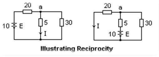
Fig. 11.1
A non-bilateral element, such as a rectifying diode, destroys reciprocity, as the circuit at the left shows. Here it is obvious that I = 0 on the right, while I ≠ 0 on the left. Even if the polarity of E is reversed so that the diode is forward-biased on the right, the currents are not reciprocal. On the left, I will be 0.21294 A, while on the right it will be 0.32824 A, as the reader can show by solving the circuits.
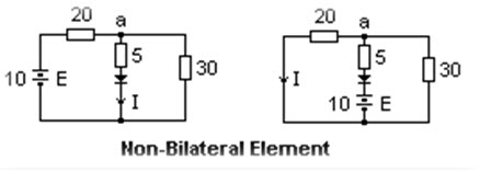
Fig. 11.2
A nonlinear element also destroys reciprocity. The circuit at the right includes a resistor whose voltage drop is proportional to the square of the current, V = 10i2. In the circuit at the left, I = 0.3798 A, while on the right I = 0.3397 A. The inclusion of controlled sources or active elements may also destroy reciprocity.
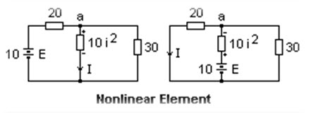
Fig. 11.3
11.1. Two-Port Networks
Consideration of reciprocity leads naturally to two-port networks. These are networks with four terminals considered in two pairs as ports at which connections are made. The emf E in the reciprocity theorem is considered to be connected to one port, say port 1, while the current is at port 2, assumed to be short-circuited. The ports result from breaking into two of the branches of the network. One terminal of each port is denoted by (+) to specify the polarity of the voltage applied at the port, and currents are positive when they enter the (+) terminal. The fundamental variables are V1, I1, V2 and I2. Any two of these variables are functions of the remaining two. For certain networks, some of the four choices are not admissible. In most cases, the variables appearing in the models are variations from DC bias conditions, not the DC variables themselves.
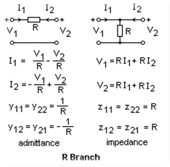
Fig. 11.4
A single resistor forms two two-ports, depending on whether it is in series or shunt. For the series resistor, it is normal to take the dependent variables as I1 and I2, and the independent variables V1 and V2. The coefficients are called the admittance parameters, since admittance is the ratio of current to voltage. If the resistor is connected in shunt, the natural independent variables are I1 and I2, while V1 and V2 are the dependent variables. The coefficients in this case are the impedance parameters, since impedance is the ratio of voltage to current. In both cases, we see that the off-diagonal or transfer coefficients are equal.
Consider the admittance model, where the coefficients are not necessarily equal to the simple ones for a single resistor. If an emf E is applied at the input, E = V1, and the output is shorted, V2 = 0, we see that I2 = y21E. If we apply the same voltage E to the output, and short the input, we have I1 = y12E. Therefore, the currents are equal, and the network is reciprocal. Reciprocity is the result of the equality of the transfer admittances. A similar result can be obtained for the impedance model, where reciprocity holds if z12 = z21, as the reader can easily show. For our simple example of a single resistor, these conditions hold.
We note that there is no impedance model for the series resistor, and no admittance model for the shunt resistor. In general, it is possible to transform from impedance to admittance and vice versa, but the determinant of the coefficients is in the denominator of the transformation formula, and for a single resistor this determinant is zero. If Δ is the determinant of the admittance coefficients, then z11 = y22/Δ, z22 = y11/Δ, z12 = y21/Δ and z21 = y12/Δ. Similar formulas hold for the inverse transformation. A full list of transformations is given in the first Reference. The conclusion is that if y12 = y21, then z21 = z12 as well. This, of course, is a general result. The particular way of modeling a network does not affect the property of reciprocity.
A popular model, especially for active elements, is the hybrid model in which the independent variables are V2 and I1. The equations for the series resistor are V1 = RI1+ V2 and I2 = -I1. The hybrid parameters for this case are h11 = R, h22 = 0, h12 = -h21 = 1. Note that the off-diagonal elements are of opposite sign in this case, but of the same magnitude. This is the mark of reciprocity in the hybrid model. As an exercise, the reader may show that for the shunt resistor h11 = 0, h22 = 1/R, and the transfer coefficients are the same as those for the series resistor.
There is a fourth model in which the output variables I1 and V1 are expressed in terms of the input variables V2 and I2: V1 = AV2 - BI2, and I1 = CV2 - DI2. Note the change in sign of I2, which is conventional so it will be in the same direction as I1 for an identity transformation A = D = 1, B = C = 0. If networks are cascaded, these matrices simply multiply. In this model, reciprocity is expressed by AD - CB = 1. This can be proved by expressing A, B, C and D in terms of the impedance parameters. A = z11/z21, B = z11z22/z21 - z12, C = 1/z21 and D = z22/z21. The result is AD - CB = z12/z21 = 1 if the network is reciprocal. It is also clear that any cascade of reciprocal networks is also reciprocal, since the determinant of the product of matrices is the product of the determinants.
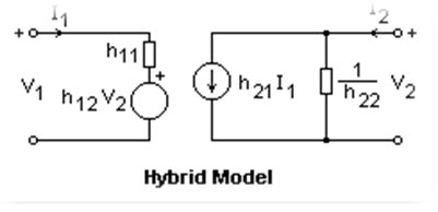 Fig. 11.5
Any model can be expressed in terms of controlled sources and impedances. This is shown at the right for they hybrid model. The h11 is represented by an impedance, h22 by an admittance. h12 and h21 are the reverse and forward transfer ratios, which are pure numbers. A current source appears in the output, while a voltage source appears in the input. This is the model often used to represent a transistor, in which h21 is usually denoted hfe or β, the base to collector current gain. The input is between base and emitter, the output between collector and emitter. Since h12 is much smaller than h21, the transistor is not reciprocal. A good approximate model results if h11 = h21 (25Ω/Ic), h12 = h22 = 0. Ic is the DC collector current. A typical value for h21 is 100. For accurate work, the hybrid coefficients can be expressed as functions of the bias conditions.
A vacuum tube can be represented by an admittance model, in which the plate current Ip is a joint function of the grid voltage Vg and the plate voltage Vp. The input port is connected to grid and cathode, the output port to plate and cathode. As long as the grid is biased negatively with respect to the cathode, Ig = 0, and two of the admittance parameters are zero. The remaining equation can be written Ip = gmVg + Vp/rp, where y12 = gm is the transconductance and 1/y22 = rp is the plate resistance. When Ip is held constant, -gmrpVg = Vp, which defines the amplification factor μ = gmrp. The same model can be used for an FET. We note that none of these models are reciprocal, which is worth remembering. These models are extremely useful in circuit design.
11.2. Proof of the Reciprocity Theorem
We wish to show that in a network of linear, bilinear elements, that is, in one constructed of ordinary impedances, that if when a voltage V is inserted in one loop the current I in another loop due to the insertion of this voltage is the same as the current at the first position due to the insertion of a voltage V in the second loop, or that the network is reciprocal. We shall do this by explicitly calculating the currents in the two cases, and observing that they are equal.
Consider the network as made up of N independent loops, of which loop 1 contains the input port, and loop 2 the output port. Let there be no emf's in the network. If there are, they can be taken care of by superposition, and we can set them all to zero for our purposes. The loop currents are Ik, k = 1 to N. If emf V is at port 1 and port 2 is shorted, then Kirchhoff's laws give Σz1kIk = V, and ΣzjkIk = 0, j = 2 to N. The current I2 can then be expressed in terms of determinants as I2 = -V det A/Δ, where the determinant in the numerator has been expanded by minors of the second column, which is all zeros except for V in the first position. A is the matrix of the z's with the first row and second column taken away. Δ is the determinant of the matrix of the zjk. Write out this solution in detail if it is not clear from this description.
Now connect V in port 2, and short port 1. The solution by determinants for I1 is -V det B/Δ, where B is the matrix of the z's with the second row and first column taken away. If we compare matrices A and B, we see that they are transposes of each other, provided that zjk = zkj. However, the off-diagonal z's are just the mutual impedances of the current loops (impedances common to a pair of loops), and do not depend on the order of the subscripts. (They are not the coefficients of an impedance model here, simply actual impedances.) Since the determinant of the transpose of a matrix is equal to the determinant of the matrix, the two solutions are the same, and I1 = I2. This proves the reciprocity theorem for networks made from linear, bilateral elements, Q.E.D.
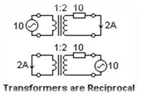
Fig. 11.6
We have proved the reciprocity theorem for a relatively limited class of networks, but it is possible to extend the theorem more widely. The figure at the right shows that reciprocity holds for ideal transformers at least. Since real transformers may be modeled by networks containing only impedances and ideal transformers, real transformers must also be reciprocal, and this extends the utility of the theorem further. Reciprocity crops up in many unexpected places, such as in electromagnetic fields and microwaves.
References
-
J. D. Irwin, Basic Engineering Circuit Analysis, 2nd ed. (New York: Macmillan, 1987). Chapter 15.
-
R. M. Kerchner and G. F. Corcoran, Alternating-Current Circuits, 3rd ed. (New York: John Wiley & Sons, 1951). p. 137f.
-
R. P. Ward, Introduction to Electrical Engineering (New York: Prentice-Hall, 1952). p. 93, Problem 24-IV.