Site pages
Current course
Participants
General
Module 1. History and types of greenhouse
Module 2.Function and features of greenhouse
Module 3.Scope and development of greenhouse techn...
Module 4.Location, planning and various components...
Module 5.Design criteria and calculations
Module 6. Construction materials and methods of co...
Module 7. Covering material and characteristics
Module 8. Solar heat transfer
Module 9. Solar fraction for greenhouse
Module 10. Steady state analysis of greenhouse
Lesson 9 Methods of construction
9.1 INTRODUCTION
At one time, greenhouses were constructed exclusively of cypress wood frames and single glass lites. Recent years have seen substantial changes in construction techniques and materials. In general, construction may be considered to fall into one of the following four categories:
1. Glass
2. Plastic film
3. Fiberglass or similar rigid plastics
4. Combination of two and three.
All of the above are generally constructed of steel or aluminum frames.
Glass greenhouses are the most expensive to construct because of both the cost of the glazing material and the requirement for a stronger framework to support the glass. In many cases, fiberglass panels are employed on the side and end walls of the structure. The building profile is generally of peaked design, with 36 and 42 ft widths, and lengths in 20 ft increments most common. This type of greenhouse is preferred by growers whose plants require superior light transmission qualities. In addition to offering the highest light quality, the glass greenhouse also has the poorest energy efficiency. Heating costs are high because of the poor insulating quality of single glazing and the high infiltration of cold air through the many "cracks" in the construction. This issue of high transmission loss has been addressed in recent years through the introduction of new, double glazing panels for glass houses. However, because of the expense of these panels and their effect upon light transmission, most glass greenhouses remain single layer.
Plastic film greenhouses are the newest variation in greenhouse construction techniques. This type of structure is almost always of the arched roof or "quonset hut" design. The roof can come all the way down to the ground or can be fitted with side walls. The side walls, if employed, and end walls are generally of fiberglass construction. Maintenance requirements for the plastic film are high in that it generally requires replacement on 3-year intervals or less, depending on the quality of the material. Most plastic film houses employ a double layer of film separated by air space. The air space is maintained by a small blower that pressurizes the volume between the layers. This double poly design is a very energy efficient approach to greenhouse design. Double poly not only reduces transmission losses (losses through the walls and roof) by 30 to 40%, but also substantially reduces infiltration (in leakage of cold air). Although the plastic film tends to lose more heat than glass through radiation, the net effect is a reduction in heating requirements compared to glass construction. Infiltration is reduced because the "cracks" present in other types of construction are eliminated through the use of the continuous plastic film. As a result, there is less opportunity for the cold outside air to penetrate the structure. The superior energy efficiency of the film construction comes at the price of reduced light transmission, however. As a result, highly light sensitive crops cannot be grown in the double-poly greenhouse as successfully as in other constructions. These greenhouses are generally constructed in 30 ft width, and 100 and 150 ft lengths.
Fiberglass greenhouses are similar in construction to the glass houses described above. They are generally of peaked roof design, but require less structural support as a result of the lower weight of the fiber glass. Heat loss of the fiberglass house is about the same as the glass house. Although the fiberglass material has a lower conductivity than glass, when considered in the overall building heat loss, this has little effect.
9.2 CONSTRUCTION OF PIPE FRAMED GREENHOUSES
The choice of construction of pipe framed greenhouses often favours low initial investment and relatively long life. Galvanized mild steel pipe as a structural member in association with wide width UV- stabilized low density polyethylene (LDPE) film is a common option of greenhouse designers.
9.2.1 Material requirement
The structural members of greenhouse are
(a) Hoops
(b) Foundation
(c) Lateral supports
(d) Poly grip assembly
(e) End frame
The following materials are required for a greenhouse having 4m × 20 m floor area:
i. GI pipe class A (25 mm diameter, 85 cm long, 30 m total length)
ii. GI pipe class B (15 mm diameter, 6.0 m long, 21 Nos.)
iii. GI sheet (20 gauge , size 90× 24 cm, 4 sheets)
iv. MS flat (25× 3 mm size, 4 m length)
v. Lateral support to end frames (10 mm diameter rod, 10 m length)
vi. Cement concrete (1: 3: 6 mix, 1.0 m3)
vii. UV- stabilized LDPE film (single layer 800 gauge, 5.4 m2/kg, 154 m2)
viii. Poly grip (channel 2000× 3.5× 4 cm, 2 Nos.; Angle 2000 ×2 ×2 cm, 2 Nos; both made from the procured 20 gauge GI sheet, key 6 mm diameter, 56 mm length)
ix. Wooden end frames (5× 5 cm wood, 0.15 m3)
x. Nuts and bolts 96 mm diameter, 35 mm long, 70 sets)
xi. Miscellaneous items like nails, hinges and latches as per requirement
9.2.2 Procedure of erection
-
Mark a 4m × 20m rectangular area on the site, preferably orienting the longer dimension in east-west direction. This rectangle will act as the floor plan of the greenhouse (Fig.9.1).
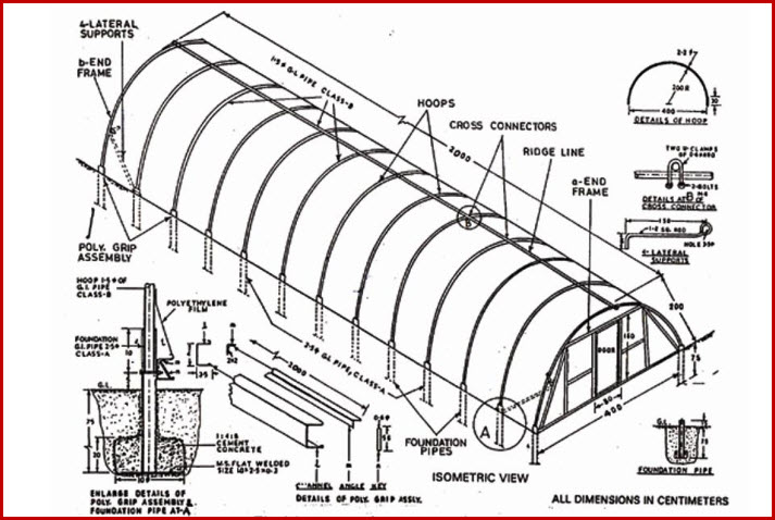
Fig 9.1 Constructional details of pipe framed greenhouse
(Source: www.tnau.ac.in )
-
Mark four points on the four corners of the rectangle.
-
Start from one corner point and move along the length of marked rectangle, marking a point every 1.25 m distance until reaching the other corner (16 bay; 17 points). The same procedure is repeated on the other side of the rectangle.
-
Dig 10 cm diameter holes up to 70 cm depth on all marked points with the help of bucket auger or a crowbar. This way a total of 34 holes on both the parallel sides of the greenhouse floor is obtained.
-
Poly grip sections formed according to the drawing into two 20m length.
-
Fix the prefabricated poly grip channels to the foundation pipes at 1.25 m spacing with the help of 6 mm diameter bolts.
-
Set these assemblies on temporary supports between the holes with the foundation pipes hanging vertically in the holes.
-
Pour cement concrete mix of 1: 3: 6 around foundation pipes in such a way that the lower 15 cm to 20 cm ends are covered in concrete. The concrete is compacted around the foundation pipes with the help of the crowbar and is allowed to cure for 2-3 days.
-
After curing, fill the soil around the foundation pipes to the ground level and compact it well.
-
Position end frames on the two ends. Mark the position of legs and dug holes for fixing of legs. Now install both the end frames.
-
Put the ringside of lateral support members on adjacent foundation pipe to the corner, and other side is hooked to the end frame.
-
Put all the hoops in the foundation pipes in such a way that straight portion of hoop is inserted into the foundation and rests on the bolt used for fixing of poly grip channel .
-
Take a 20 m long ridge line by spacing 15 mm diameter pipes together. Put the 20m long pipe at the ridge line of the hoops.
-
Use cross connectors on the ridge line pipe, in such a way that one half of it remains on the one side of the hoop and the other half on the other side.
-
Put two bolts of 6 mm diameter in the holes provided in the ends of cross-connector. Tie a few of them with the help of nuts.
-
Repeat the same procedure for joining all the hoops with ridge line pipe.
-
While forming cross-connectors, the distance between the cross-connectors or hoops should be maintained 1.25 m centre to centre. This poly grip mechanism will provide a firm grip of the ridge line pipe and hoops at right angles without allowing for slippage.
-
Spread polyethylene film over the structure from one end to the other end without wrinkles and keeping the edges together.
-
Place polyethylene film between the poly grip channel and right angle strip and secure them under pressure with the help of iron rods. The film is stretched gently and fixed on the other parallel side by poly grip. This way the polyethylene is secured on both the longer sides.
-
On the other two remaining ends, polyethylene is nailed to the end frames using wooden battens and nails.
-
The remaining portion of the end frames is covered with polyethylene film, which is secured with wooden battens and nails.
-
Mechanical ventilation, heating and cooling equipment is installed on the frames as per the crop requirement.
9.3 CONSTRUCTION OF HIGH TUNNEL GREENHOUSE :A photographic View (Source: www.sare.org) :
Refer PPT ( http://10.112.63.9/moodle/server/moodle/course/modedit.php?update=1751&return=0&sr=0 ) (high tunnel construction)
References:
1. http://www.hort.vt.edu : Rafferty et al. Greenhouses
2. www.tnau.ac.in : Design criteria and constructional details of greenhouses
3. www.sare.org : Lewis W Jett. Design and Construction of High Tunnels in West Verginia
Last modified: Saturday, 21 December 2013, 5:20 AM