Site pages
Current course
Participants
General
Module 1. History and types of greenhouse
Module 2.Function and features of greenhouse
Module 3.Scope and development of greenhouse techn...
Module 4.Location, planning and various components...
Module 5.Design criteria and calculations
Module 6. Construction materials and methods of co...
Module 7. Covering material and characteristics
Module 8. Solar heat transfer
Module 9. Solar fraction for greenhouse
Module 10. Steady state analysis of greenhouse
Lecture 12 Heat Transfer for Solar Energy Utilization
12.1 INTRODUCTION
To estimate the size, the efficiency and cost of equipment necessary to transfer a specified amount of heat in a given time, a heat transfer analysis must be made. The dimension of solar collector depends not so much on the amount of heat to be transmitted but rather on the rate at which heat is to be transferred under given external conditions. From engineering point of view, the determination of rate of heat transfer at a specified temperature difference is the key problem in sizing a solar collector.
Heat transfer occurs mainly by three mechanisms viz. conduction ,convection and radiation (Fig.12.1) The heat transfer may be accompanied by other physical phenomena such as heat generation within the medium, vapour condensation, liquid evaporation etc.
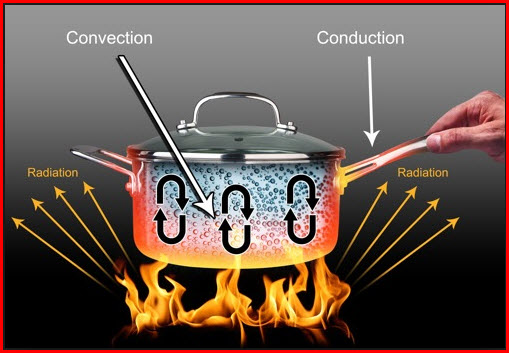
Fig 12.1 Mechanism of heat transfer
(Source: www.spectrose.com)
12.2 CONDUCTION
The heat transfer takes place between the objects that are in direct contact with each other. For example, when you place a pot on the stove, the hot coils come in contact with the metal pan, making it hot.
The basic heat conduction equation is:
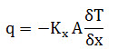 ….. (12.2.1)
Where,
q is the rate of heat transfer
Kx is the thermal conductivity of the material in the direction x
A is the area normal to the direction of heat flow and
δT/δx is the temperature gradient in the direction of flow
12.3 RADIATION
Radiation is a process by which heat flows from a body at higher temperature to a body at lower temperature when the bodies are separated in space or even a vacuum exists between them. The term radiation is generally applied to all kinds of electromagnetic wave phenomena, but in heat transfer only those phenomena that are the result of temperature and can transport energy through a medium such as air or space are of interest. The energy transmitted in this way is called radiant heat. Radiation is the mode of heat transfer by which the sun transfers energy to the earth. The quantity of energy leaving a surface as radiant heat depends on the absolute temperature and the nature of the surface. A perfect radiator, so called black body emits radiant energy from its surface at a rate q given by
q=AσT4 ………(12.3.1)
Where,
A is area of the body
T is the absolute temperature °K
σ is a constant known as Stefan Boltzmann Constant
= 487.6 x 10⁻¹⁰ kcal/m2.hr.K4
= 56.7 x 10⁻⁹ W/m2.K4
Real bodies do not meet the specifications, of an ideal radiator and emit radiation at lower rate than do black bodies. The ratio of the radiation emission of a real body to the radiation emission of a black body at the same temperature is called the emittance. Thus a real body emits radiation at a rate
q=εAσT4 ……………..(12.3.2)
where e is the average emittance of the surface.
If radiation exchange takes place between two grey bodies e.g. two large, parallel plates with areas A1 and A2 the rate of heat transfer between them is given by,
qr net = A1Fσ(T14-T24)……….(12.3.3)
where F is the geometrical factor of the surface with respect to the other.
Equation for radiant heat transfer can be written as
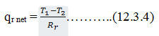 ………..(12.3.4)
where the resistance to radiation heat transfer is
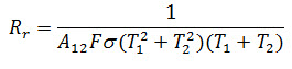 …….(12.3.5)
For example, for infra- red radiation between two parallel, large, flat plates of the same area with emittance e1 and e2
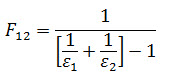 ……(12.3.6)
For simplification of linear equation radiant heat transfer coefficient hr is given by,
q= hr (T1-T2) ….(12.3.7)
then it is clear that,
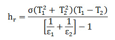 …. (12.3.8)
Reception of radiant energy: Radiation impinging on the surface of a body may be partly absorbed, partly transmitted and partly reflected as shown in fig 12.2
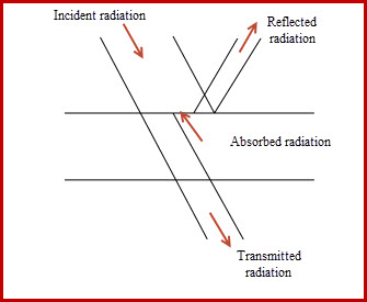
Fig 12.2 Total radiation utilized in different ways
The fraction of the incident radiation absorbed is called the absorptivity a. Similarly, the fraction of the incident radiation reflected is called as the reflectivity, r and the fraction transmitted is called as transmissivity,t.
If I denotes the total incident radiation per unit time per unit area of surface, and Ia, Ir and It, represent respectively the amount of radiation absorbed, reflected and transmitted then,
 …….(12.3.9)
 ……(12.3.10)
 ..…..(12.3.11)
Also, Ia + Ir+ It=I
Hence a+r+t =1 ……(12.3.12)
The relationship given in equation (12.3.12), hold for surfaces or for layers of finite thickness. The following points are to be noted:
i. The values of a, r andt are always positive and lie between the limits 0 and 1 i.e. 0 £ r,t,a £ 1
ii. r=0 (i.e. t+a=1) represents a non-reflecting surface, r=1 (i.e t= a=0) represents perfect reflector.
iii. t=0 (i.e r+a =1) represents an opaque surface, t=1 (i.e. r = a=0) represents a perfectly transparent surface.
iv. a=0 (i.e.r+t =1) represents non absorbing surface, a=1 (i.e r=t=0) represents perfectly absorbing surface.
12.4 REFLECTIVITY
Reflectivity of opaque surface depends not only on the temperature and the properties of the surfaces but also on the wavelength and directions of the incident and reflected radiation. Based on the nature of the reflected radiation, reflecting surfaces may be classified as diffuse or specular.
Diffuse reflector: A surface is called diffuse reflector if intensity of the reflected radiation is constant, for all angles of reflection and is independent of the direction of the incident radiation.
Specular reflector: If the incident and reflected rays lie symmetrically with respect to the normal to the surface at the point of incidence and the reflected beam is contained in a solid angle equal to the solid angle of the incident beam.
Rough surface behaves like a diffuse reflector where as polished metallic surface behave like a specular reflector. No real surface is either perfectly diffuse to perfectly specular.
White surface: A diffuse surface which reflects all incident energy (i.e. r=1), is termed as a white surface.
Non Reflecting surface: if r=0 it is non- reflecting surface.
Opaque surface: If r=0, t=0 and a=1 then it is opaque surface.
Black surface: Surface which absorbs all incident energy is called as a black surface. Black surface is extensively used in radiation heat transfer work as an idealized body with which the radiation characteristics of real bodies can be conveniently compared.
12.4.1 Reflectivity of translucent materials: Since in most applications there will be a slab of materials involving two faces, reflection at both faces shall have to be considered.
12.4.1.1 Reflection at interfaces: Fresnel has given the relationship for the reflection of non- polarized radiation on passing from one medium to another. (Fig. 12.4.1).
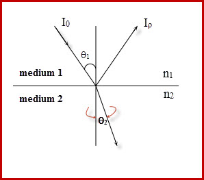
Fig 12.4.1 Angle of incidence and reflection in two media.
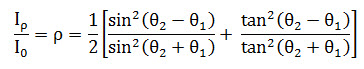 …………(12.4.1)
Where,
θ1 is the angle of incidence
θ2 is the angle of refraction
In the expression the two terms in the square brackets represent the reflection for each of the two components of polarization. The angles q1 and q2 are related to the indices of refraction.
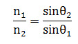 ………(12.4.2)
Thus if the angle of incidence and refraction indices are known from equation (12.4.2) one can calculate the reflectance of the single interface.
For radiation at normal incidence,
θ1=θ2=0,
Combining equation 12.4.1 and 12.4.2 gives
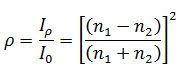 …………..(12.4.3)
12.5 TRANSMISSIVITY
Transmissivity like reflectivity and absorptivity, is a function of the wavelength and the angles of incidence of the incoming radiation. Other variables which effect the transmissivity are the refractive index n and tile extinction coefficient k of the medium but strictly speaking, both n and K are also functions of the wavelength l.
For t=1, the medium is perfectly transparent however, most real materials are only partially transparent with 0<t<1.
Transmissivity in partially transparent (i.e. translucent) materials is dependent both upon the reflection and absorption of radiation. The problem is usually tackled in two stages:
i. The transmissivity ‘tr’ is first calculated considering reflection alone.
ii. The transmissivity ‘ta’ is then calculated considering absorption alone.
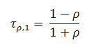
The transmissivity r, allowing for both reflection and absorption is then given by,
![]() ……….(12.5.1)
……….(12.5.1)
It is found that the equation (12.5.1) is a satisfactory relationship for use in the design of solar collectors.
12.5.1 Calculation of tp
Cover materials used in solar applications require the transmission of radiation through a slab or film of material and there are thus two interfaces per cover to cause reflection loss. In this situation, the depletion of the beam at the second
surface is the same as that at the transmission through one cover. First, for each component of polarization, assuming cover interfaces are with air on both sides. Neglecting absorption in the slab as shown in Fig.12.5.1. and considering unit incident beam, (1- r) of the incident beam reaches the second interface. Of this, (1 - r)2 passes through the interface and r(1- r) is reflected back to the first, and so on. Summing up the resulting terms, the transmittance for a single cover neglecting absorption is,
 …….(12.5.2)
For system of n covers, all of same material
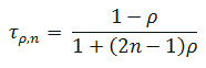 …….(12.5.3)
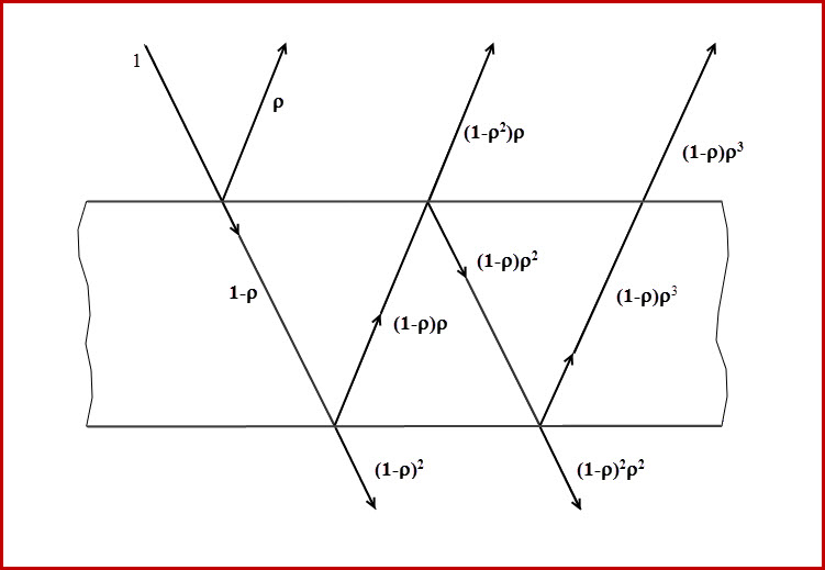
Fig 12.5.1 Transmission through one cover
12.5.2 Calculation of ta
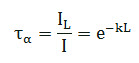
The absorption of radiation in partially transparent (i.e. translucent) materials is described by the Bouger's law,
dI = Ik dx ………(12.5.4)
where dI is the diminution in the radiation intensity, I is the local value of intensity, k is the extinction coefficient and x is the distance travelled by the radiation. Assuming k to be constant in the range of l of the solar spectrum. Equation (12.5.4) can be integrated to give,
 …………….(12.5.5)
.Note that 'ta’. is the transmittance considering only absorption and L is the actual path of the radiation through the medium. For n covers,
![]() …………….(12.5.6)
…………….(12.5.6)
when angle of refraction q2 is given,
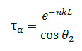 …………….(12.5.6)
The value of k for glass varies from about 0.01/cm for absolutely clear "whiter-white" glass to 0.321cm for poor quality glass with a greenish cast of the edges. Note that ta is the transmittance considering only absorption and L is the actual path of the radiation through the medium. Now the transmittance allowing for both reflection and absorption can be obtained by the equation (12.5.1).
12.6 Transmittance-Absorptance Product
For solar collector analysis, it is necessary to evaluate the transmittance-absorption product (t.a). Of the radiation passing through the cover system and striking the plate, some is reflected back to the cover system. However, all this radiation is not lost since some is reflected back to the plate. This is illustrated in Fig.12.6.1, where ‘t’ is the transmittance of the cover system as can be known from equation (12.5.1) and a is the angular absorptance of the absorber plate. ‘t.a’ is absorbed by the absorber plate and (1 - a)t, is reflected back to the cover systems. The reflection from the absorber plate is probably more diffuse than specular so that the fraction (1 - a)t that strikes the cover plate is diffuse radiation and (1 -a)t. rd is reflected back to the absorber plate. The quantity rd refers to reflection of the cover plate for incident diffuse radiation that may be partially polarized due to reflections as it is passed through the cover system. Hence summation yields,
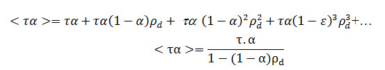
….……(12.6.1)
Due to reflection <ta> will be greater than ta.
For incidence angle of 60°, rd is approximately 0.16, 0.24, 0.29 and 0.32, for one, two, three and four glasses respectively.
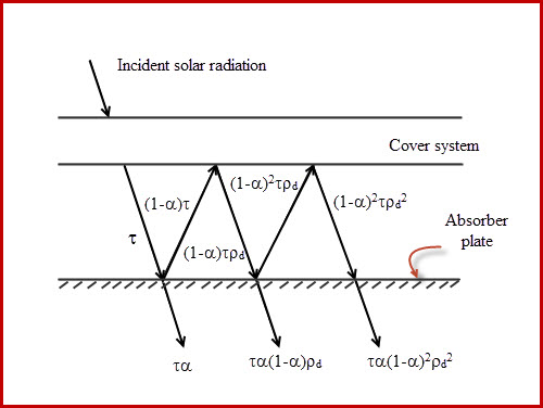
Fig 12.6.1 Absorption of solar radiation by absorber plate
The radiation absorbed in the glass cover system is not completely lost to the system. Slightly 'raising the temperature for the cover plates serves to reduce the rate of upward heat loss from the collector plate. This reduction in collector losses due to absorption in the cover can be conveniently thought of as an artificial increase in the transmittance. This give rise to the term "effective transmittance", or more exactly the 'effective' transmissivity-absorptivity product (ta)e. The effective transmissivity absorptivity product, (ta)e is calculated from the following formula;
![]() ……(12.6.2)
……(12.6.2)
where α's are constants and the subscripts 1, 2, 3 etc. refer to the first (outer), second, third etc. layers of transparent cover system.
12.7 CONVECTION
Convection is a process that transfers heat from one region to another by motion of a fluid. The rate of heat transfer by convection qc, between a surface and a fluid can be calculated from the relation
qc = hc A(Ts-Tf) …………(12.7.1)
where,
qc= rate of heat transfer by convection kcal/hr
A= base area of heat transfer by convection m2
Ts= surface temperature °C
Tf = fluid temperature °C
hc = convection heat transfer coefficient kcal/hr.m2.°C
Thermal resistance to convective heat transfer, Rc is given by,
 ………….(12.7.2)
The surface of the solar energy collector losses heat by mechanism of convection and radiation to the surrounding. The total rate of heat transfer q is given by equation
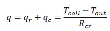 ………(12.7.3)
Where,
Rcr = combined resistance for the two mechanisms,
Tcoll = average temperature of collector surface
Tout = outside air temperature
12.7.1 Dimensionless numbers used for convection studies :
1. Nusselt Number: non dimensional heat transfer coefficient

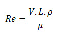
2. Reynold’s Number: ratio of inertia to viscous forces, used in the description of forced convection, where the fluid has an initial velocity with respect to the heated surface.
3. Prandtl number: ratio of molecular diffusivities of momentum with respect to heat.

4. Grashof number: ratio of buoyant to viscous forces: replace Re in case of natural convection
5. Rayleigh number: ratio of thermal buoyance to viscous inertia
Ra= Gr. Pr
Where,
L= Plate spacing
k= Thermal conductivity
β= Volumetric coefficient of expansion of air
ΔT= temperature difference between plates
V= fluid velocity
μ= dynamic velocity
Cp= specific heat
ρ= fluid density
γ= kinematic viscosity
References:
1. Rai G.D.(2011): Solar Energy Utilization Khanna Publisher
Last modified: Thursday, 6 March 2014, 9:12 AM