Site pages
Current course
Participants
General
Module- 1. Introduction of food plant design and ...
Module- 2. Location and site selection for food pl...
Module- 3. Food plant size, utilities and services
Module- 4. Food plant layout Introduction, Plannin...
Module- 5. Symbols used for food plant design and ...
Module- 6. Food processing enterprise and engineer...
Module- 7. Process scheduling and operation
Module 8. Building materials and construction
19 April - 25 April
26 April - 2 May
Lesson 8. Layout Design Procedure
The design of any layout is governed by a number of factors and the best layout is the one that optimizes all the factors. The factors influencing any layout are categorized into the following eight groups:
-
The material factor: includes design, variety, quantity, the necessary operations, and their sequence.
-
The main factor: includes direct workers, supervision and service help, safety and manpower utilization.
-
The machinery factor: includes the process, producing equipment and tools and their utilization
-
The movement factor: includes inter and intradepartmental transport and handling at the various operations, storage and inspection, the materials handling equipment.
-
The waiting factor: includes permanent and temporary storage and delays and their locations.
-
The service factors: include service relating to employee facilities such as parking lot, locker rooms, toilets, waiting rooms etc.; service relating to materials in terms of quality, production control, scheduling, dispatching, waste control; and service relating to machinery such as maintenance.
-
The building factor: includes outside and inside building features and utility distribution and equipment.
-
The change factor: includes versatility, flexibility and expansion
Each of the above mentioned factors comprise a number of features and the layout engineer must review these in the light of his problem. Usually the layout design process is a compromise of these various considerations to meet the overall objectives in the best possible manner.
The overall layout design procedure can be considered to be composed of four phases Viz.,
Phase I: Location
Phase II: General Overall Layout
Phase III: Detailed layout
Phase IV: Installation
Some important guidelines that help in the layout design are:
Plan from whole to details
First plan the ideal and then move to the practical aspects
Material requirements should be central to the planning of process and machinery.
modify the process and machinery by different factors to plan the layout
Though there is always an overlap in the different phases of layout design the major steps that have to be followed in the layout design are outlined as follows:
state the problem in terms of its objective, scope and factors to be considered
Collect basic data on sales forecasts, production volumes, production schedules, part lists, operations to be performed, work measurement, existing layouts, building drawing etc.
Analyze data and present it in the form of various charts
Plan the production process and its arrangement
Plan the material flow pattern and develop the overall material-handling plan
Estimate plant and machinery requirements Select material handling equipment
Determine storage requirements
Design and plan activity relationships
Plan auxiliary and service facilities including their arrangement
Determine space requirements and allocate activity areas
Develop plot plan and block plan i.e. integrate all plant operations
Develop detailed layouts and plan building along with its arrangement
Evaluate, modify and check the layouts
Install layouts and follow up
The Systematic Layout Planning (SLP) procedure as presented by Francis and White (1974) is shown in Figure 8.1. We see that once the appropriate information is gathered, a flow analysis can be combined with an activity analysis to develop the relationship diagram. Space considerations when combined with the relationship diagram lead to the construction of the space relationship diagram. Based on the space relationship diagram modifying considerations and practical limitations, a number of alternative layouts are designed and evaluated.
8.1 Data collection
The development of any layout is dependent on the quality and quantity of facts that we have about the various factors influencing it. The data collection phase is not a one-time effort but an ongoing function. The data for overall plan is to be collected at initial stages where as the data for detailed layouts may be obtained at a later stage, the facts have to be obtained regarding various materials and processes, the flow routing and sequencing, space requirements and different activities and relationships.
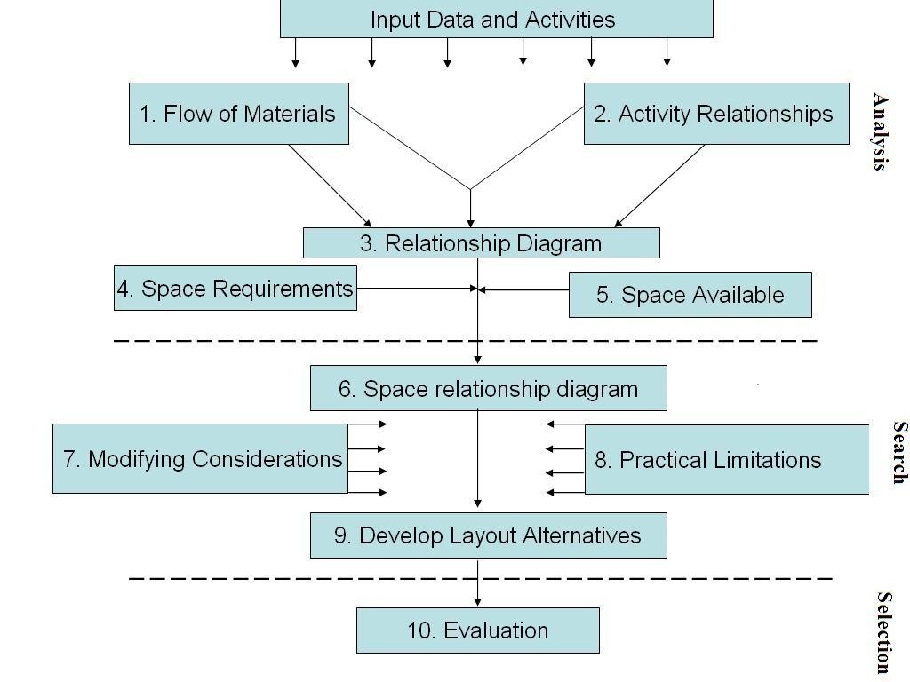
Figure 8.1 Systematic layout planning procedure
8.2 General guidelines / considerations
8.2.1 Site layout:
A good site layout provides safe and economical flow of materials and personnel. A material sheet for the site is therefore prepared which then allows the various processes to be positioned relative to one another. The services (e.g. boiler house, effluent plant etc.) are then added in the most convenient positions. The central buildings (administration, canteen, laboratories etc.) are placed in such a manner that the distances traveled by personnel to use them are minimized. Finally the road and rail systems are marked in. Typical sizes and clearances for the site layout are given in Tables 8.1 to 8.3. Having established site constraints and standards, a more detailed site layout can be made. The site layout thus prepared should then be considered to see whether the layout is consistent with safety requirements and that it assists action in any emergency as also the constraints and standards have not been violated.
Broad guidelines for preparation of the site layout are given below:
Minimize the distance that materials have to travel to or from stores or during processing
Separate the raw material unloading and finished product loading facilities
Isolate the hazardous operations
Locate storage areas close to unloading and loading facilities
locate boiler room, power station, cooling towers, water pumping station etc. on periphery but adjacent to the area of largest use
The usual clearances between pipes including flanges and lagging and between pipes and other objects should be 25 mm but this should be increased if hot pipes run near plastic pipes, cables etc.
Steam and water mains, electricity and telephone cables etc. should, in general, run parallel to the road system and should avoid going through plant area
Locate office building close to the main entrance
Provide adequate parking facilities for vehicles waiting to load / unload, cars, scooters etc.
Plan roads in such a manner that the vehicles do not pass through process areas. Ideally, outside of a plant should be accessible on all four sides by road
Workshop and general stores should be located within easy access of the processing units.
Table 8.1 Typical clearances between various units for preliminary site layouts
|
Area |
To |
Clearance, m |
|
Plant areas |
To the adjacent unit, main roads or boundary |
15 |
|
Boilers and furnaces |
15 |
|
|
Blow down stacks with flares |
30 |
|
|
Gas holders |
30 |
|
|
Cooling towers |
30 |
|
|
Effluent plants |
15 |
|
|
|
|
|
|
Loading areas |
To process units |
15 |
|
Ware houses |
30 |
|
|
Offices and canteens |
30 |
|
|
Medical center |
30 |
|
|
Garage |
30 |
|
|
Fire station |
30 |
|
|
Work shops |
30 |
|
|
Main roads |
12 |
|
|
|
|
|
|
Main roads |
To building line excluding loading bays |
9 |
|
|
15 |
|
|
|
15 |
|
|
|
|
|
|
Roads |
Center line to loading bay head room |
7 |
|
Paved areas and paths |
4 |
|
|
Rail roads |
5 |
Table 8.2 Typical areas and sizes for preliminary site layouts
|
Administration |
10 m2 |
per administration employee. |
|
Work shop |
20 m2 |
per workshop employee |
|
Laboratory |
20 m2 |
per laboratory employee |
|
Canteen |
1 m2 |
per dining place |
|
3.5 m2 |
per dining place including kitchen and store |
|
|
Medical center |
0.1 - 0.15 m2 10 m2 minimum |
per employee depending on complexity of service |
|
Fire station (housing 1 fire, 1 crash, 1 foam, 1 generator and 1 security ,vehicle) |
500 m2 |
per site |
|
Garage (including maintenance) |
100 m2 |
per vehicle |
|
Main roads |
10 m |
wide |
|
Side roads |
7.5 m |
wide |
|
Pathways |
1.2 m |
wide upto 10 people /minute |
|
|
2 m |
wide for 10 people / minute (near offices, canteen etc.) |
|
Road turning circles |
900 turn |
11 m radius |
|
|
T junction |
7.5 m radius |
|
|
minor roads |
4 m radius |
|
Minimum railroad curve |
56 m |
inside curve radius |
|
Cooling towers per tower |
0.04 m2/ kWh |
mechanical draught |
|
|
0·08 m2 / kWh |
natural draught |
Table 8.3 Typical constraint allowances for preliminary plant layout
|
Equipment |
Safety |
Horizontal |
Vertical |
Construction/ Erection/ General |
|
Centrifuges Crushers Mills |
|
3 m |
2 m + L |
5 m access corridor |
|
Dryers |
|
1.5 m + L |
2 m + L |
2.5 m to building |
|
Columns |
|
1.5 m |
|
3 m between adjacent columns |
|
Furnaces and fired heaters |
15 m to hazard |
3 m |
|
2 widths (center to center adjacent heaters ) |
|
Reactors Stirred vessels |
15 m to hazard |
1.5 m |
3 m + L |
4 m access area 40 m2for each 30 cm3 reactor volume |
|
Heat exchanger (horizontal) |
|
1.5 m +I channel 1.5-2 m shell side |
1.5 m |
|
|
Tanks |
15 m to hazard |
1/2 dia (avg.) between tanks |
3 m |
|
|
Pumps |
|
2 m motor end 1.5 m sides |
|
|
|
Filters |
|
1.5 m + L |
|
|
|
Compressors |
|
1.5 m + L |
3 m + L |
2 widths (center to center adjacent compressors ) |
L: is the length of the longest internal part of the equipment that must be removed for maintenance or operation.
8.2.2 Plant layout
In general, a most economical plant layout is that in which spacing of the main equipment items is such that it minimizes the interconnecting pipe work and structural steel work. As a general rule, layout should be as compact as possible with all equipment at ground level and it should conform to access and safety requirements. The major considerations are listed below:
Equipment should be laid to give maximum economy of pipe work and supporting steel. Normally, they should be laid out in a sequence to suit the process flow, but exceptions to this arise from the desirability to group certain items such as tanks or pumps or perhaps to isolate hazardous operations.
In general, high elevation should only be considered when ground space is limited or where gravity flow of materials is desired.
Equipment items which are considered to be a source of hazard should be grouped together and wherever possible should be located separately from other areas of the plant.
Provide sufficient clear space between critical and mechanically dangerous or high temperature equipment to allow safety of operating or maintenance personnel.
The equipment needing frequent internal cleaning or replacement of internal parts should be laid out for ease of maintenance.
Elevation to the underside of the pipe bridges and racks over paved areas should be at least 4 m.
8.2.3 Layout of equipment
Thought should be given to the location of equipment requiring frequent attendance by operating personnel and the relative position the control room to obtain the shortest and most direct routes for operators when on route operation. However, the control room should be in a safe area. Some important considerations involved in locating a few key equipment items are listed below:
Mixing vessels can be laid out in a straight line, in pairs or staggered.
In evaporators using barometric leg type condensers, barometric leg should be at least 10 mm from the vessel base. This is usually situated on the ground floor. For multiple effect evaporators, place the individual effects as close as possible to minimize vapor lines. Vapor liquid separator is accommodated without increasing the distance between effects. The layout requirements for crystallizers are similar to those for evaporators.
Furnaces should be located at least 15 m away from other equipment. Ample room need to be provided at the firing front for the operation of the burner and burner control panel.
Where there are a large number of heat exchangers, they are often put together in one or more groups. Location should provide a layout, which is convenient to operate and maintain. Horizontal clearance of at least 1.5 m should be left between exchangers or exchangers and piping. Floating head heat exchangers require an installation length of at least 2.5 times the tube length. Air cooled exchangers are located adjacent to the plant section they serve.
Pumps in general should be located close to the equipment from which they take suction. Changes in direction of the suction line should be at least
0.6 m from the pump. As far as possible, clearances and piping should provide free access to one side of the motor and pump. Clearances between pumps or pumps and piping should be at least 1.2 m for small pumps (18 kW) and 1.5 m to 2 m for large pumps. Pumps handling hot liquid (60 °C) should be at least 7.5 m from pumps handling volatile liquids.
8.2.4 Space determination
In the layout planning process the space is allotted to different activities.
The theoretical minimum space, a plant can occupy, is the total volume of its various components. Various constraints prevent the attainment of this minimum. Such constraints include allowing adequate clearances for access during operation and maintenance and to allow safe operation. While determining the space consideration should be given to the following.
Operating equipment
Storage
Service facilities
Operators/workers
Allowance must be made for space between adjacent equipment/machines for movement of the worker, work-in-process, maintenance personnel etc.
Last modified: Friday, 23 August 2013, 9:51 AM