Site pages
Current course
Participants
General
Module 1:Water Resources Utilization& Irrigati...
Module 2:Measurement of Irrigation Water
Module 3: Irrigation Water Conveyance Systems
Module 4: Land Grading Survey and Design
Module 5: Soil –Water – Atmosphere Plants Intera...
Module 6: Surface Irrigation Methods
Module 7: Pressurized Irrigation
Module 8: Economic Evaluation of Irrigation Projec...
19 April - 25 April
26 April - 2 May
LESSON 19 Contour Bench Levelling and Earthwork Quantities Computation
In this lesson, purpose of construction of contour benches, its design and computation of earth work quantities are presented. Irrigation in undulating fields and steep slope is a very difficult task. Rainfall erosion and moisture conservation can be controlled and retained by forming contour benches. Earthwork computation is an important task in land levelling.
19.1 Contour Bench Levelling
Contour bench levelling is a method for cutting length of slope to a desired grade and preparing land for irrigation. The undulated field is cut into a number of steps approximately by using contours; each step is levelled and made as an independent area. Thus a series of steps are formed in successive elevations around the slope. Benches are used for forming the border, furrow and check basin the slope. The contour bench levelling provides controlled irrigation water flow on the flat slopes and for efficient irrigation. Contour bench levelling controls erosion from rainfall, and permits soil building processes thereby resulting in increase of fertility and improved soil structure. The flat benches provide greater opportunity time for infiltration thereby reducing the quantity of irrigation water needed to meet plant requirements.
19.1.1 Construction of Contour Benches
The components of bench cross-section are shown through Fig. 19.1. Selecting the proper cross section for contour benches is one of the most important steps of planning for contour bench construction.
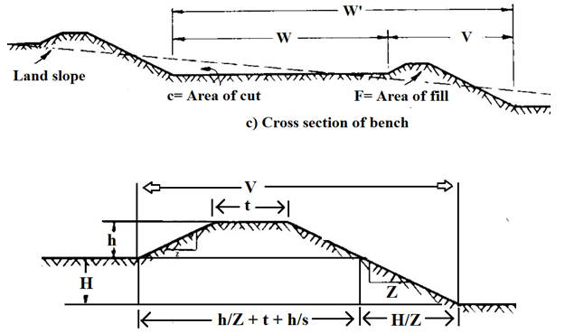
Fig. 19.1. Cross section of bench and bund. (Source: Michael, 2010)
Let W be the bench width of the farmable area. This width should be such that it can accommodate the widest of farm equipment to be used for farming.
The other parameters are:
Wʹ = overall bench width (m)
W = width of cultivable strip (m)
t = top width of dike (m)
h = height of dike (m)
H = vertical interval between benches (m)
Z = side slope of dike (dimensionless)
S = slope of land (dimensionless)
The relationship between W, W![]() and H can be expressed as:
and H can be expressed as:
W![]() = H/S (19.1)
= H/S (19.1)
or, H = W![]() S (19.2)
S (19.2)
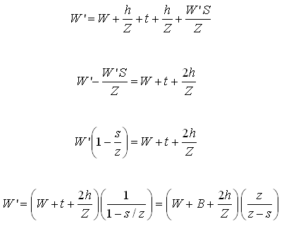 (19.3)
The side slopes of dike (Z) should have stable side slopes. The side slope of 2:1 is normally provided. The area where stones are presents in the field much steeper slope can be used. Stones should be used to support the bund. Top width of the dike, (t) should be sufficient to prevent further lowering of its height by trampling or by other sources.
It is a usual practice to keep the top width of dike equal to the vertical interval between benches.
t = H (19.4)
Example 19.1: A trapezoidal bund of 80 m long is to be constructed having bottom width as 4 m and top width as 2 m. The height of one end of bund is 1.2 m and that of the other end is 1.5 m. Determine the volume of earth fill for making bund.
Solution:
The volume of earth fills for making bund 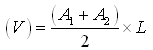
Area of one end of bund (A1) = ½(4+2) 1.2 =3.6 m2
Area of other end of bund (A2) =½(4+2) 1.5 = 4.5 m2
![]()
V = 324.00 m3
Hence volume of earth fill = 324.00 m3
Example 19.2: The random field ditch drains are to be used for removal of drainage water. The plan, profile and cross section are shown Fig.19.1. Estimate the volume of earth work for cutting.
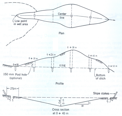
Fig. 19.2. Layout of random field drain for computing the earth work in cutting. (Source: Schwab et al., 1993)
Solution:
The levelling instrument was used to obtain the depth of cut for the ditch grade of 0.15 per cent. The procedure used to compute earth work is illustrated in the following Table 19.1.
|
Station (m) |
Cut (m) |
Top Width (m) |
Cross- sectional area (m2) |
Average Cross- sectional area (m2) |
Distance (m) |
Volume of cut (m3) |
|
0+00 |
0 |
0 |
0 |
|
|
|
|
0+10 |
0.20 |
2.0 |
0.40 |
0. 2 |
10 |
2.00 |
|
0+20 |
0.35 |
3.5 |
1.23 |
0.82 |
10 |
8.20 |
|
0+30 |
0.70 |
7.0 |
4.9 |
3.07 |
10 |
30.70 |
|
0+40 |
0.45 |
4.5 |
2.03 |
3.47 |
10 |
34.70 |
|
0+50 |
0.00 |
0.0 |
0.0 |
1.02 |
10 |
10.20 |
|
Total |
85.80 |
|||||
The total volume of earthwork in cutting is 85.8 m3
19.2 Earthwork Quantities Computation
Earthwork quantities need to be computed for desired land levelling method and for generated cross section. The common methods for computing earthwork quantity are: end area method, prismoidal and four point method.
a) End Area Method
The areas of cuts and fills on the profiles or grid lines are used to compute the volume between the adjacent profile or grid lines, given by relationship
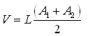 (19.5)
In which,
V = volume of cut or fill, m3
L = distance between profiles or lines, m
A1 = area of cut or fill in the first profile or line, m2
A2 = area of cut or fill in the second profile, m2
b) Prismoidal Formula
A precise method of computing the volume of earthwork in land levelling makes use of the prismoidal formula
![]() (19.6)
(19.6)
In which
V = volume of earthwork, m3
L = perpendicular distance between end planes, m
A1= area of the first end plane, m2
A2 = area of the second end plane, m2
Am = area of middle section parallel to end planes (m2)
c) Four – Point Method
A commonly used method called the four-point method is sufficiently accurate for land grading. Volume of cuts for each grid square is given by
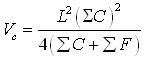 (19.7)
where,
Vc = volume of cut, m3
L = grid spacing, m
C =sum of cut on the four corners of a square grid, m
F = sum of fill on the four corners of a square grid, m
For computing Vf the volume of fills, (ƩC)2 in the numerator of equation 19.7 is replaced by (ƩF).
Example 19.3: Compute the balancing depth (volume of earthwork in cutting is equal to volume of earthwork in filling) for a canal having a bed width as 8 m with side slopes of 1:1 in cutting and 2:1 in filling. The bank embankments are kept 2 m higher than the ground level (berm level) and crest width of embankments is 2.0 m.
Solution:
The channel section is shown in Fig 19.3. Let d1 be the balancing depth, i.e. the depth for which excavation and filling becomes equal.
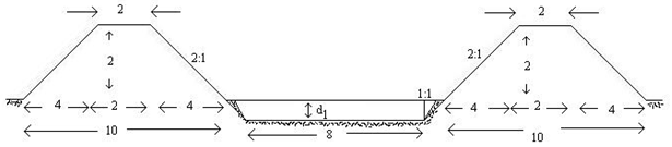
(All dimensions are in meter)
Fig. 19.3. Cross section of a canal with embankment.
Let the length of canal be L meter.
Area of cutting (A1) = (8+d1) d1
Volume of earthwork in cutting V1= [(8+d1).d1].L (19.8)
Area of cross section of two embankments 
Volume of earthwork in filling in construction of embankments = 24 L m2
Equating equations (19.8) and (19.9), we get
[(8+ d1) d1]L = 24L (19.10)
or, d1+ 8 d1 – 24 = 0
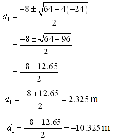
Ignoring infeasible –ve sign, we get = 2.325 m
Balancing depth = 2.325 m
References
Michael, A. M. (2010). Irrigation Theory and Practice, Vikas Publishing House PVT Ltd, Noida, India.
Suggested Readings
Anderson, C. L., Halderman, A.D., Paul, H. A. Rapp, E. (1980). Land Shaping Requirements. (In Design and Operation of Farm Irrigation Systems, Edited by Jensen, M.E), ASAE Monograph 3, St. Joseph, MI: 281-344.
Schwab, G. O., Fangmeier, D. D., Elliot, W. J., and Frevert, R. K. (1993). Soil and Water Conservation Engineering. John Willey & Sons, Inc., New York, USA.
Last modified: Saturday, 15 March 2014, 6:04 AM