Site pages
Current course
Participants
General
Module 1: Introduction and Concepts of Remote Sensing
Module 2: Sensors, Platforms and Tracking System
Module 3: Fundamentals of Aerial Photography
Module 4: Digital Image Processing
Module 5: Microwave and Radar System
Module 6: Geographic Information Systems (GIS)
Module 7: Data Models and Structures
Module 8: Map Projections and Datum
Module 9: Operations on Spatial Data
Module 10: Fundamentals of Global Positioning System
Lesson 14 Microwave Remote Sensing
14.1 Microwave Sensor
The microwave region of interest to remote sensing covers the electromagnetic radiation of wavelength extending from a few millimeters to meters, in frequency interval from 40,000 to 300 MHz. The sensors are broadly classified as active and passive sensors. In passive mode, unlike in the visible and infrared regions the radiation from the sun does not play any direct part. Thus, the microwave sensors can operate during day and night. Due to its higher wavelength, the atmospheric haze, cloud, light rain (does not pass through heavy rain), dust/smoke is transparent to microwave, thus providing observation in all weather and environmental conditions. In addition, microwave remote sensing provides information about sea wind and wave direction derived from frequency characteristics, doppler effect, polarization, backscattering, etc which cannot be observed by visible and infrared sensors.
Microwave reflection or emission has no direct relation to the counterparts in visible or thermal portions of the spectrum for an object. Passive microwave sensing is similar in concept to thermal remote sensing. Due to higher wavelength, the field of view for a microwave sensor must be large to detect enough energy to record a signal. Most passive microwave sensors are therefore characterized by low spatial resolution.
14.2 Antenna
An antenna is a transducer to transform from a high frequency electric current to radio waves and vice-versa. An antenna is used to transmit and receive microwaves. In optical remote sensing the EM radiations used to focus with lenses as it cover wavelength 0.3 micrometer to 15 micrometer. Due to high wavelength, the microwaves are focused with antenna rather than lens.
Before we consider the realization of antennas, let us get familiarized with some of the terminologies used in antenna engineering.
Radiation pattern
A radiation pattern defines the variation of the power radiated (or received) by an antenna as a function of the direction away from the antenna. In an ideal isotropic antenna the radiation pattern is same in all directions; the plot of the antenna pattern would be formed as a sphere. Antennas with isotropic radiation patterns don't exist in practice, but are sometimes discussed as a means of comparison with real antennas. Radiation patterns are three-dimensional. However, they are usually measured in two orthogonal principal planes either in polar or rectangular coordinates. The patterns are normalized to the maximum value at 0 dB. In general, for any particular antenna for remote sensing, the pattern has a main lobe, where most of the energy is concentrated and sidelobes (Fig. 14.1), which are desirable.
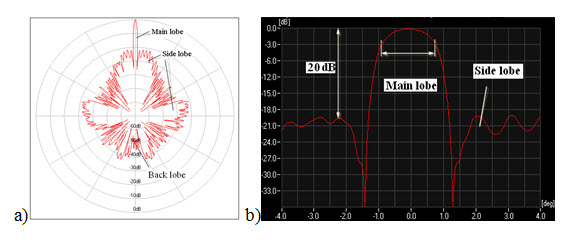
Fig. 14.1. Radiation pattern in a) polar coordinate, b) Cartesian system. (Source: www.radartutorial.eu/18.explanations/ex42.en.html)
Antenna gain
It is a measure of ability of the antenna to ‘focus’ the in a particular direction. Gain of an antenna is described as how much power is transmitted in a direction of peak radiation to that of an isotropic antenna. The total power of the antenna cannot be changed; but the energy can be redistributed in a particular direction of interest. Thus it is expressed relative to the performance of an isotropic antenna, which radiates equally in all direction and usually expressed in decibels (dB). An antenna with a gain of 3 dB means that the power received far from the antenna will be 3 dB higher than what would be received from an isotropic antenna with the same input power.
The gain G of an antenna with losses is given by,
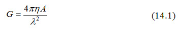
Where, is the efficiency, that is, the ratio of the total power radiated by the antenna to the net power fed to the antennas and λ is the wavelength.
A is the physical aperture area; for a particular aperture 
Beam width
Two points can be found on either side of the maximum power of the main lobe in the radiation pattern which represents half of the maximum power. These points are referred to as half power points. The angular range between the half power points is known as beam width. Since half power is 3 dB, the half power beam width is usually to as 3 dB beam width. The beam width (β) is a function of the wavelength λ and the antenna aperture D.
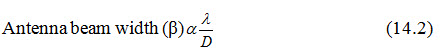
That is beam width will be narrow if large antenna dimension increases.
Typical antennas in microwave remote sensing could be passive type of microwave radiometer, active types of microwave altimeter, scatterometer and imaging radar. There are three major types of antenna: horn antenna, parabolic antenna and array antenna.
Horn antenna
It consists of a flaring metal waveguide shaped looks like a horn to direct radio waves in a beam. Due to its shape it is named as horn antenna. The flared portion can be square, rectangular, or conical. The maximum radiation and response corresponds with the axis of the horn. Horn antennas often have a directional radiation pattern with a high antenna gain, which can range up to 25 dB in some cases, with 10-20 dB being typical. Horn antennas have a wide impedance bandwidth, implying that the input impedance is slowly varying over a wide frequency range. Horn antennas have very little loss, so the directivity of a horn is approximately equal to its gain. This type of antenna is used in microwave radiometer.
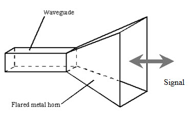
Fig. 14.2. Horn antenna.
(Source: searchmobilecomputing.techtarget.com/definition/horn-antenna)
Parabolic antenna
A parabolic antenna uses a parabolic reflector, a curved surface with the cross-sectional shape of a parabola, to direct the microwaves. The reflector is illuminated by a feed, usually a horn, which is located at the focal point of the reflector (Fig. 14.3. a). The main advantage of a parabolic antenna is that it has high directivity. Parabolic antenna has some of the highest gains, that is they can produce the narrowest beamwidth, of any antenna type. It is used in microwave radiometers, altimeters and scatterometers.
Array antenna
An array antenna is composed of multiple element arrays for example, linear array, area array or nonformal array. The element antennas are half-wavelength dipoles, microstrip patches and wave guide slot (Fig. 14.3. b). The advantages of array antenna are to enable beam scanning without changing the looking angle of each array antenna and to generate an appropriate beam shaping by selective excitation of current distribution of each element. The array antenna is used in synthetic aperture radar (SAR) and real aperture radar.
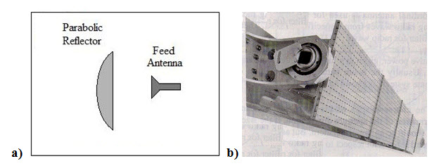
Fig. 14.3. a) Parabolic antenna; b) array antenna.
(Source: www.antenna-theory.com/antennas/reflectors/dish.php)
14.3 Passive Microwave Sensors
Passive microwave remote sensing is similar in concept to thermal remote sensing. All objects emit microwave energy of low magnitude. A passive microwave sensor detects the naturally emitted microwave energy within the field of view. This emitted energy is related to the temperature and moisture properties of the emitting object or surface. Passive microwave sensors are typically radiometers or scanners. The microwave energy recorded by a passive sensor can be emitted by the atmosphere (1), reflected from the surface (2), emitted from the surface (3), or transmitted from the subsurface (4), (Fig. 14.4.).
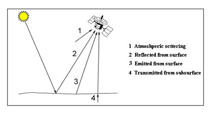
Fig. 14.4. Components of passive microwave signal.
The energy being too low in magnitude, in passive remote sensing the instantaneous field of view (IFOV) must be large to detect this energy, therefore most passive sensors are characterized by low spatial resolution. Microwave radiometer is a passive microwave sensor.
Passive microwave radiometers generally records energy in the region between 0.15 cm and 30 cm (between 1 GHz and 200 GHz), well beyond the thermal infrared region (3-14 micrometer). But the microwave is also radiated by thermal radiation from the objects on the earth. Thus microwave radiometers used in passive microwave remote sensing are also affected by atmosphere. In the Fig. 14.5 the atmospheric window for microwave remote sensing is shown. Even measurements are at atmospheric window frequencies, the accurate estimation of surface radiance needs correction for these absorptions and emissions from the atmosphere. Most surface sensing radiometers include frequency channels also sensitive to water vapour and liquid water – mainly to correct for their effects. For observation of atmospheric parameters, frequencies are selected, which generally fall above 50 GHz.
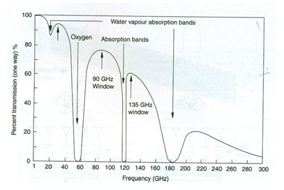
Fig. 14.5. Atmospheric window in microwave remote sensing.
(Source: Joseph, 2005).
Applications of passive microwave remote sensing include meteorology, hydrology, and oceanography. By looking "at", or "through" the atmosphere, depending on the wavelength, meteorologists can use passive microwaves to measure atmospheric profiles and to determine water and ozone content in the atmosphere. Hydrologists use passive microwaves to measure soil moisture since microwave emission is influenced by moisture content. Oceanographic applications include mapping sea ice, currents, and surface winds as well as detection of pollutants, such as oil slicks (Source: www.nrcan.gc.ca/earth-sciences/geography-boundary/remote-sensing/fundamentals/2021).
14.4 Active Microwave Sensors
Active microwave sensors are generally divided into two distinct categories: imaging and non-imaging. The most common form of imaging active microwave sensors is RADAR (Radio Detection And Ranging), which is essentially characterizes the function and operation of a radar sensor. The sensor transmits a microwave signal towards the target and detects the backscattered portion of the signal. The time measurement gives the distance of the target from the sensor and hence gives the location of the target and the amount of energy backscattered depends on the target properties and hence gives a measure of some of the target characteristics (Fig. 14.6).
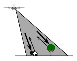
Fig. 14.6. Active microwave remote sensing.
(Source: www.nrcan.gc.ca/earth-sciences/geography-boundary/remote-sensing/fundamentals/2021)
Non-imaging microwave sensors include microwave altimeters and scatterometers. In microwave scatterometer, the sensors sends short microwave pulse and measures the amount of energy backscattered from the surface of earth, used to make precise quantitative measurements of the amount of energy backscattered from targets. The amount of energy backscattered is dependent on the surface properties (roughness) and the angle at which the microwave energy strikes the target. As an example scatterometer measurements over ocean surfaces can be used to estimate wind speed based on the sea surface roughness. Ground-based scatterometers are used extensively to accurately measure the backscatter from various targets in order to characterize different materials and surface types. This is analogous to the concept of spectral reflectance curves in the optical remote sensing. Whereas microwave altimeters look straight down at nadir below the platform and thus measure height or elevation (if the altitude of the platform is accurately known).
Keywords: Microwave, Antenna, Antenna gain, Beam width, Radiometer, Scatterometer, Altimeter.
References
Joseph, G., 2005, Fundamentals of Remote Sensing, Second Edition, Universities Press (India) Pvt. Ltd., pp. 220.
www.radartutorial.eu/18.explanations/ex42.en.html; Dec. 18, 2012
searchmobilecomputing.techtarget.com/definition/horn-antenna; Dec. 18, 2012
www.antenna-theory.com/antennas/reflectors/dish.php; Dec. 18, 2012
www.nrcan.gc.ca/earth-sciences/geography-boundary/remote-sensing/fundamentals/2021; Dec. 18, 2012
www.nrcan.gc.ca/earth-sciences/geography-boundary/remote-sensing/fundamentals/2021; Dec. 18, 2012
Suggested Reading
Bhatta, B., 2008, Remote sensing and GIS, Oxford University Press, New Delhi, pp. 164-182.
Lillesand, T. M., Kiefer, R. W., 2002, Remote sensing and image interpretation, Fourth Edition, pp. 616-705.
www.jars1974.net/pdf/05_Chapter04.pdf
www.iki.rssi.ru/asp/pub_sha1/Sharch03.pdf
www.jars1974.net/pdf/04_Chapter03.pdf
Last modified: Friday, 24 January 2014, 9:23 AM