Site pages
Current course
Participants
General
Module 1. Perspective on Soil and Water Conservation
Module 2. Pre-requisites for Soil and Water Conse...
Module 3. Design of Permanent Gully Control Struct...
Module 4. Water Storage Structures
Module 5. Trenching and Diversion Structures
Module 6. Cost Estimation
5 April - 11 April
12 April - 18 April
19 April - 25 April
26 April - 2 May
Lesson 24. Earthen Dam Drainage and Failure
24.1 Drainage System
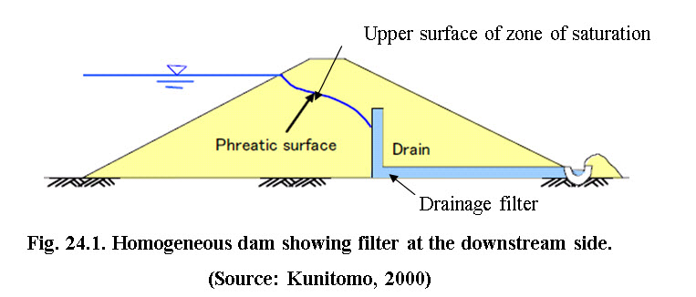
Drainage in earthen dams is primarily provided to bring the phreatic line (upper surface of zone of saturation) in the embankment well within the downstream face so that water does not seeps through the body of the dam. It is achieved using the filter material at the downstream end of the earthen embankment (Fig.24.1). It drains the excess water inside the confining structure and thus reduces the pore pressure and thus internal erosion
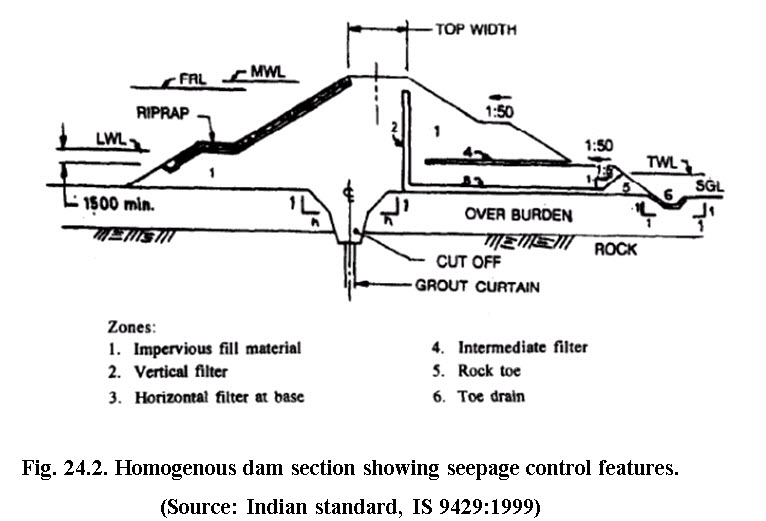
The code of practice recommended by Indian standards (IS 9429:1999) lists different type of filters based of their relative placement in the embankment. These are presented in Fig. 24.2.
24.2 Criteria for Selection of Drainage Features
The drainage features primarily address the problem of seepage force in form of pore water pressure and piping.
24.2.1 Impervious Fill Material
The seepage control in the dam body is achieved either by providing a barrier or control in drainage. The impervious fill material can act asa barrier to the seepage flow through the body of embankment dam.
24.2.2 Inclined/Vertical Filter with Horizontal Filter
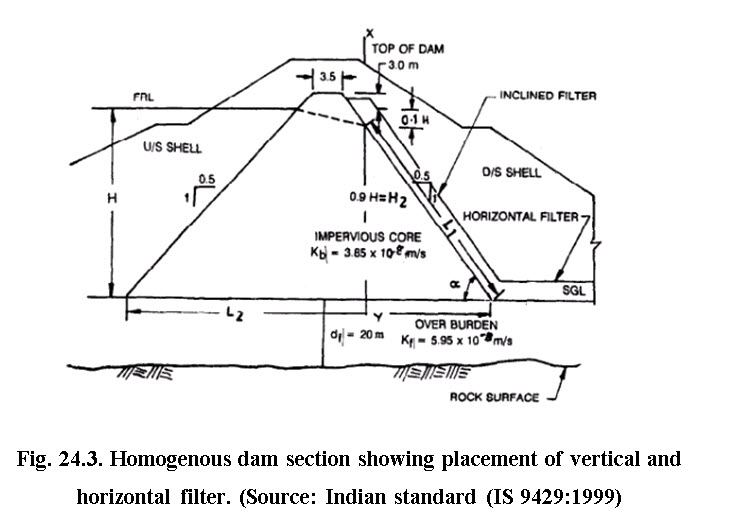
The inclined or vertical filters abutting downstream face of the impervious core are provided to collect seepage water to keep the downstream shell relatively dry. The top level of the vertical filter should be kept as equal to the top of the impervious core level at least. The minimum thickness should be kept as one meter. At the base, this filter should be connected to the horizontal filter that will ultimately carry the seepage water to the toe drain (see Fig. 24.3).
24.2.3 Horizontal Filter
Horizontal filter collects seepage water from body of the dam through inclined or vertical filter and transmits it to the toe drain and thus minimize the risk of piping from the dam base. Horizontal filter is usually provided in the downstream side of the homogenous dam. A minimum slope of 1 in 100 towards toe filter has to be maintained for quick disposal of seepage water to the toe drain. A minimum thickness of one meter is required for the horizontal drainage.
24.2.4 Intermediate Filter
Horizontal layer of filter in both upstream and downstream at intermediate level is required in the cases where pore pressure exerted during construction and sudden draw down in expected. Italso helps in reducing pore pressure rise after prolonged rainfall. The thickness and vertical interval are decided on the basis of height, permeability of earth of dam body and filter. However, provision of 0.6 m thickness at 6.0 m interval is considered as adequate for small earthen dam. This filter can be extended upto outer slope of the embankment but care should be taken to avoid the connection with vertical/inclined filters.
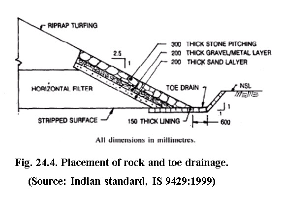
24.2.5 Rock Toe
The major function of the rock toe is to protect the lower part of downstream embankment.
24.2.6 Toe Drain
Toe drain (Fig. 24.2) is provided at the downstream side of the earthen dam to collect seepage from the horizontal filter or inner cross drains, through the foundation as well as the rain water falling on the face of the dam.
24.3 Design Criteria for Filter Material
The filter material used for drainage system should satisfy the following criteria.
Filter material should be more pervious than base material
The particle of base material should not clog the voids of filter material
Based on percentage of particles finer than 75 micron, the base soil are graded (Table 24.1).
Table 24.1. Categories of base soil
|
Sl. No. |
Catagory |
% finer than 75 micron |
|
i |
1 |
>85 |
|
ii |
2 |
40-85 |
|
iii |
3 |
15-39 |
|
iv |
4 |
<15 |
(Source: IS-9429)
To satisfy the permeability requirement of the filter material, D15 of the filter material should be equal to or higher than 5 times D15 of base soil and should not be less than 0.1 mm. Table 2 presents filtercriteria for different base material.
Table 24.2. Criteria for filters
|
Catagory |
Base soil description and per cent finer than 75 micron |
Filter criteria |
|
1 |
Fine silt and clay, more than 85% finer |
D15(F) ≤ 9D15(B) ≥ 0.2 mm |
|
2 |
Sand, silt, clay and silty and clayey sand, 40-85% finer |
D15(F) ≤ 0.7 mm |
|
3 |
Silty and clayey sands and gravel, 15-39% finer |
4D15(B) - 0.7mm but should not be less than 0.7 mm |
|
4 |
Sand and gravel, less than 15% finer |
D15(F) ≤ 4D15(B) |
(Source: IS-9529)
The configuration of the filter zones, however, will depend upon the type of embankment:
In a modified homogenous dam, the filter is generally placed as a blanket of sand and fine gravel on the downstream foundation area, extending from the cutoff/core trench boundary to the edge of the downstream toe and then taken to safe discharge by the toe drains.
In a zoned dam, the filter is placed between the core and the downstream shell zone. A longitudinal ‘chimney’ drain of gravel material collects the intercepted seepage flow and carries it to the base of the chimney. The transverse drains then conveys the water to the toe drains outside the embankment.
Design criteria has been given by Terzaghi

Provided that the filter material does not contain more than 5% material finer than 0.75mm.


The particle size distribution curve of both i.e. filter and base material should be parallel.
24.4 Causes of Failure of Earthen Dams
Like most of engineering structures, earthen dams may fail due to faulty design, improper construction and poor maintenance practices, etc.
The various causes of failure may be classified as:
a) Hydraulic failure
b) Seepage failure
c) Structural failure
24.4.1 Hydraulic Failure
Hydraulic failure accounts for over 40% of earth dam failure and may be due to one or more of the following:
(i) By Overtopping: When free board of dam or capacity of spillway is insufficient, the flood water will pass over the dam and wash its downstream.
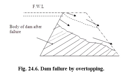
Fig. 24.6. Dam failure by overtopping.
(Source:http://theconstructor.org/water-resources/failure-of-earthfilldams/2287/)
(ii) Erosion of Downstream Toe: The toe of the dam at the downstream side may be eroded due to heavy cross-current from spillway buckets ortail water. When the toe of downstream is eroded, it will lead to failure of dam. This can be prevented by providing a riprap at downstream side up to a height above the tail water depth. Also, the side wall of the spillway should have sufficient height and length to prevent possibility of cross flow towards the earthen embankment.
(iii) Erosion of Upstream Surface: During winds, the waves developed near the top water surface may cut into the soil of upstream dam face which may cause slip of the upstream surface leading to failure. For preventing against such failure, the upstream face should be protected with stone pitching.
(iv) Erosion of Downstream Face by Gully Formation: During heavy rains, the flowing rain water over the downstream face can erode the surface, creating gullies, which could lead to failure. To prevent such failures, the dam surface should be properly maintained. All cuts\cracks should be filled on time and surface should be well grassed to reduce the effect of surface runoff. Berms could be provided at suitable heights and proper drainage should be maintained.
24.4.2 Seepage Failure
Seepage always occurs in the dams. If the magnitude is within design limits, it may not harm the stability of the dam. However, if seepage is concentrated or uncontrolled beyond limits, it will lead to failure of the dam. Following are some of the various types of seepage failure.
(i) Piping through Dam Body: Seepage starts through the poor soils in the body of the dam, small channels are formed which transport dam’s material downstream. As more materials are transported downstream, the channels grow bigger and bigger which could lead to wash out of dam.
(ii) Piping through Foundation: When highly permeable cavities or strata of gravel or coarse sand are present in the dam foundation, it may lead to heavy seepage. The concentrated seepage at high rate will erode soil present in the foundation which will cause increased flow of water and soil. As a result, the dam will settle or sink leading to failure.
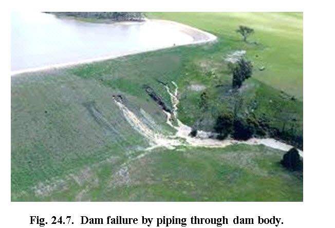
(Source: http://www.civeng.unsw.edu.au/node/913)
(iii) Sloughing of Downstream Side of Dam: The process of failure due to sloughing starts when the downstream toe of the dam becomes saturated and starts getting eroded, causing small slump or slide of the dam. The small slide leaves a relative steep face, which also becomes saturated due to seepage and also slumps again and forms more unstable surface. The process of saturation and slumping continues, leading to failure of dam.
24.4.3 Structural Failure
About 25% of failure is attributed to structural failure, which is mainly due to shear failure causing slide along the slopes. The failure may be due to:
(i) Slide in Embankment: When the slopes of the embankments are too steep, the embankment may slide resulting in its failure. This occurs when there is a sudden drawdown or drastic decrease in the upstream water level due to some means, which is critical for the upstream side. Because of this, development of extremely high pore pressures takes place which decreases the shearing strength of the soil. The downstream side can slide especially when dam is full. In this case upstream embankment failure is not as serious as downstream failure.
(ii)Foundation Slide: When the foundation of an earthfill dam is composed of fine silt, clay, or similar soft soil, the whole dam may slide due to water thrust. If fissured rocks, such as soft clay, or shale exist below the foundation, the side thrust of the water pressure may shear the whole dam and cause its failure. In such failure the top of the dam gets cracked and the lower slopes moves outward and forms large mud waves near the dam heel.
(iii) Faulty Construction and Poor Maintenance: If during construction, the compaction of the embankment is not properly done, it may lead to failure.
(iv) Earthquake may Cause the Following Types of Failure to Earth fill Dams:
Cracks may develop in the core wall, causing leakages and piping failure.
Slow waves may set up due to shaking of reservoir bottom, and dam may fail due to overtopping.
Settlement of dam which may reduce freeboard causing failure by overtopping.
Sliding of natural hills causing damage to dam and its appurtenant structures.
Fault movement in the dam site reducing reservoir capacity and causing overtopping.
Shear slide of dam.
Failure of slope pitching.
References
-
Suresh, R. (1993). Soil and Water Conservation Engineering. Standard Publishers and Distributors, New Delhi.
-
Indian standard (1999). Drainage system for earth and rock fill dam – Core of
-
practice: IS-9429
-
Kunitomo, N. (2000). Design and Construction of Embankment Dams. Dept. of
-
Civil Eng., Aichi Institute of Technology.
Internet references
nptel.iitm.ac.in/courses/Webcourse-contents/.../pdf/m4l07.pdf
www.dcr.virginia.gov/stormwater_management/.../Chapter_3-01.pdf
Suggested Reading
Suresh, R. (1993). Soil and Water Conservation Engineering. Standard Publishers and Distributors,New Delhi.
Indian standard (1999). Drainage system for earth and rock fill dam – Core of
practice: IS-9429
nptel.iitm.ac.in/courses/Webcourse-contents/.../pdf/m4l07.pdf
www.dcr.virginia.gov/stormwater_management/.../Chapter_3-01.pdf
Last modified: Friday, 14 February 2014, 6:44 AM