Site pages
Current course
Participants
General
MODULE 1. Analysis of Statically Determinate Beams
MODULE 2. Analysis of Statically Indeterminate Beams
MODULE 3. Columns and Struts
MODULE 4. Riveted and Welded Connections
MODULE 5. Stability Analysis of Gravity Dams
Keywords
5 April - 11 April
12 April - 18 April
19 April - 25 April
26 April - 2 May
LESSON 31. Stability Analysis of Gravity Dams: Stresses
31.1 Introduction: In this lesson we will derive expressions for the base pressure and stresses developed in a gravity dam.
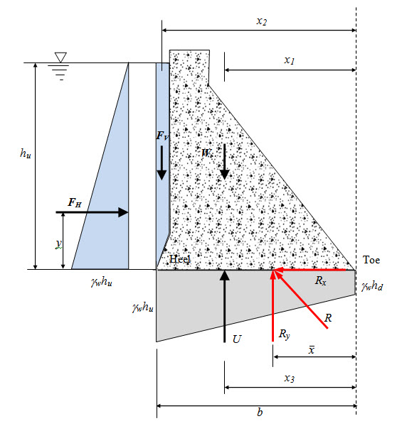
Fig. 31.1.
In the above figure let R be the resultant force cutting the base at a distance \[\bar x\] from the toe of the dam. The components of R in x and y direction are obtained as,
\[{R_x}={F_H}\] (31.1)
\[{R_y}=W + {F_V} - U\] (31.2)
\[\bar x\] is obtained as,
\[\bar x={{{M_{toe}}} \over {R{}_y}}\] (31.3)
The eccentricity of from the centre of the base is given by, \[e = {b {\left/2} - \bar x\] .The nominal stress at any point on the base is the sum of direct stress and bending stress.
The direct stress is always compressive and given by,
\[{\sigma _{cc}} = {{{R_y}} \over b}\] [per unit length of the dam] (31.4)
Bending moment about the centre of the base is, \[M={R_y} \times e\] . Corresponding bending stress at a distance x from the centre of the base is given by,
\[{\sigma _{bc}}=\pm {{Mx} \over I}\] (31.5)
Where, I is the second moment of area of the base per unit length of the dam. I is given by,
\[I={{1 \times {b^3}} \over {12}}={{{b^3}} \over {12}}\] (31.6)
Therefore total normal stress at a distance x from the centre of the base is,
\[{p_n}={\sigma _{cc}} + {\sigma _{bc}}={{{R_y}} \over b} \pm {{Mx} \over I} = {{{R_y}} \over b} \pm {{12Mx} \over {{b^3}}}\] (31.7)
The resulting moment produces tension at heel and compression at toe.
Therefore,
\[{p_{nheel}}={{{R_y}} \over b} - {{12\left( {{R_y} \times e} \right)\left( {{b {\left/2}})} \over {{b^3}}}={{{R_y}} \over b}\left({1-{{6e} \over b}} \right)\] (31.8)
\[{p_{toe}}={{{R_y}} \over b} + {{12\left( {{R_y} \times e} \right)\left( {{b{\left/2}})} \over {{b^3}}}={{{R_y}} \over b}\left( {1 + {{6e} \over b}} \right)\] (31.9)
The distributions of normal stress at the base of the dam for three different situations are shown in Figure 31.2.
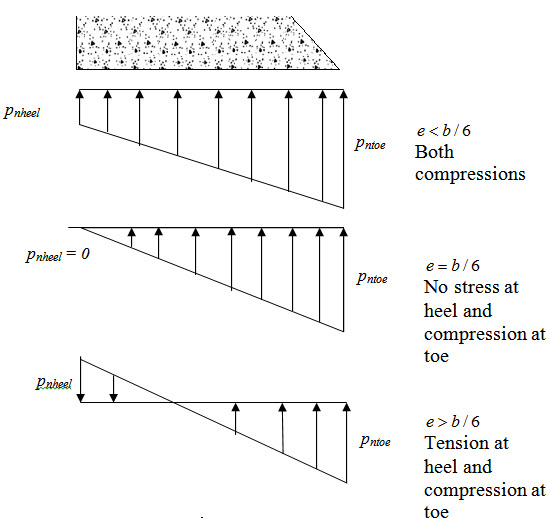
Fig. 31.2.
Suggested Readings
Garg, S.K. Irrigation Engineering and Hydraulic Structures. Khanna Pub.
Last modified: Saturday, 21 September 2013, 10:33 AM